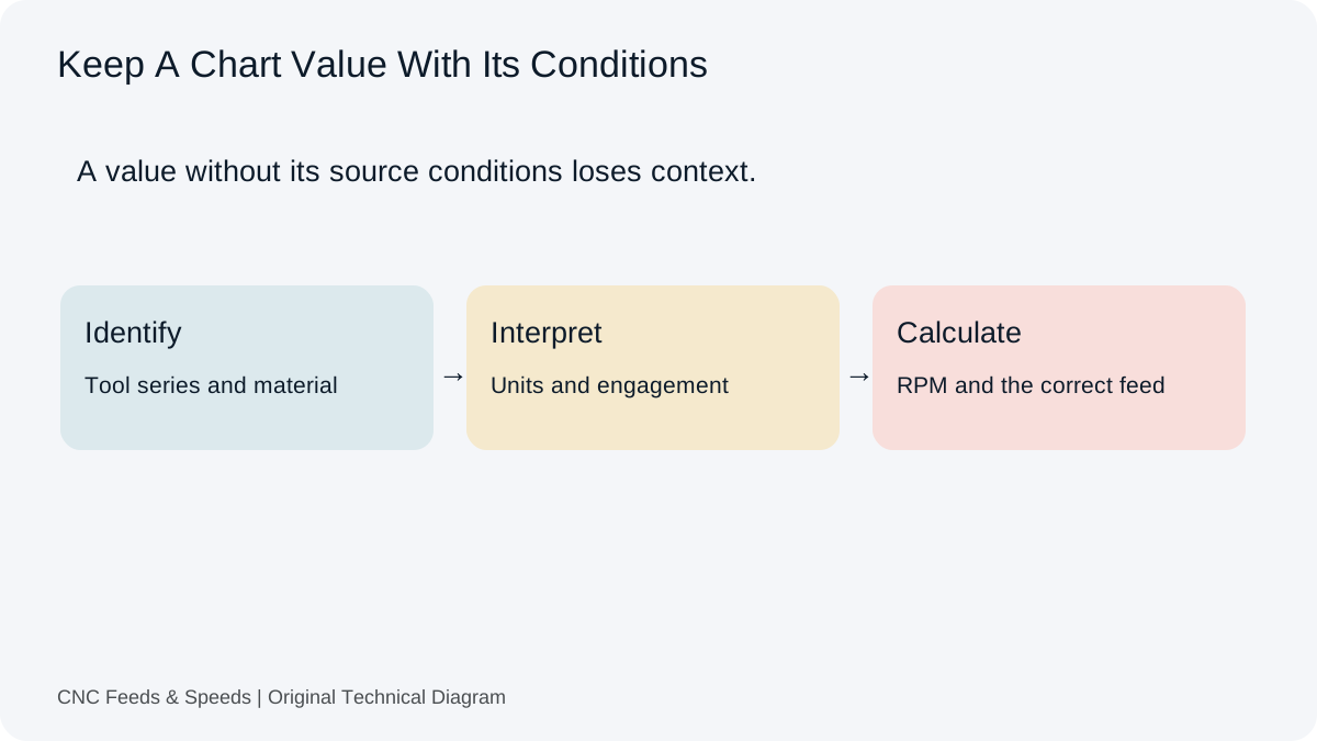
Before using a cutting chart, identify the tool family, material condition, operation and units attached to its values. A column marked feed may mean feed per tooth, feed per revolution or linear feed. Establish that definition before converting the chart into RPM and a machine feed command.
Read the chart title first
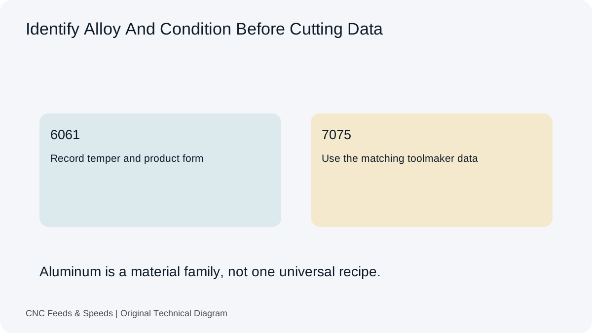
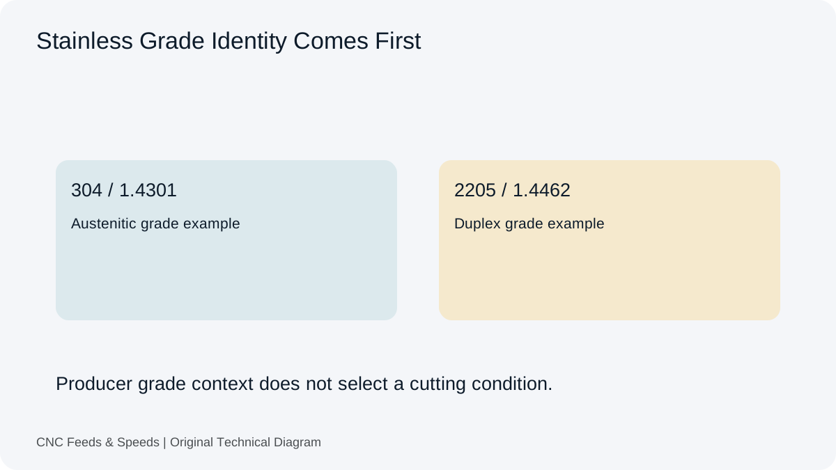
Start by identifying the tool family and material group represented by the chart. A table for a carbide end mill is not automatically applicable to HSS, and a table for aluminum is not interchangeable with austenitic stainless steel. Check whether the chart is for roughing, finishing, slotting, drilling, or another specific operation.
Find the unit definitions
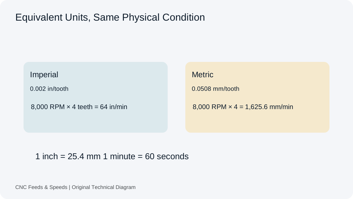
Look for SFM, m/min, RPM, mm/rev, in/rev, mm/tooth, or in/tooth. Then identify whether diameter is entered in inches or millimetres. Most conversion mistakes happen because a user finds the right number but applies the wrong unit relationship.
Understand what the chart is actually giving you
Some tables provide a cutting speed range. Others provide chip load by diameter, feed per revolution, or a complete RPM/feed example. Do not assume a column labelled “feed” means the same thing across different suppliers. Write the variable name and unit beside the value before using it.
Convert cutting speed into RPM
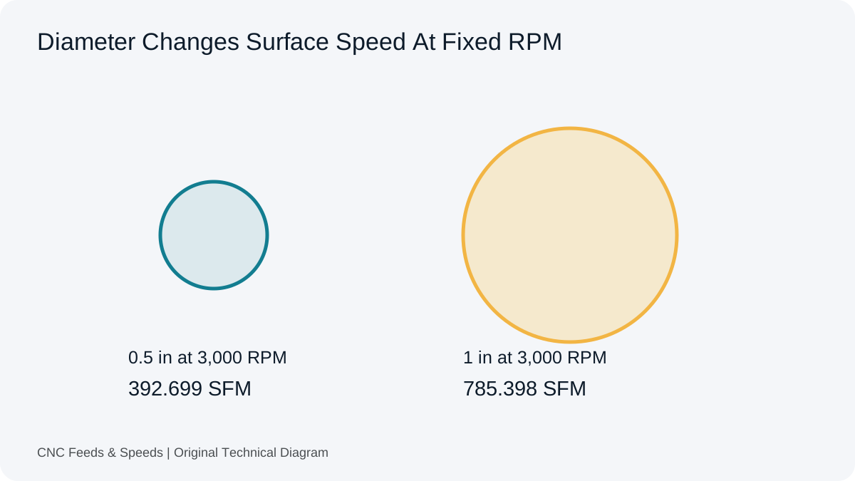
For metric work, RPM = (1000 × Vc) ÷ (π × D). For imperial SFM data, RPM = (12 × SFM) ÷ (π × D). This is the point where a chart value becomes a spindle command. Use the spindle speed calculator to check the conversion before carrying it into the feed calculation.
Convert chip load into feed
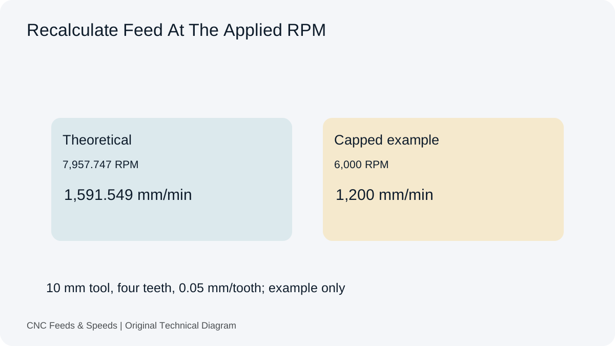
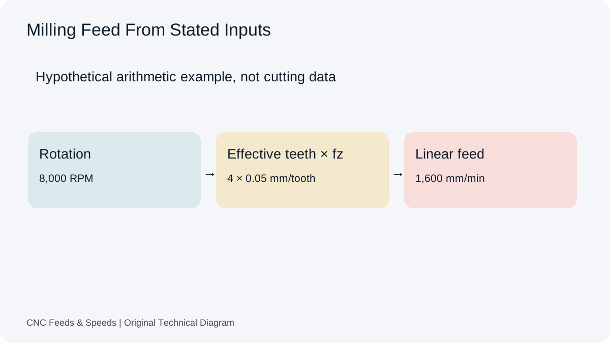
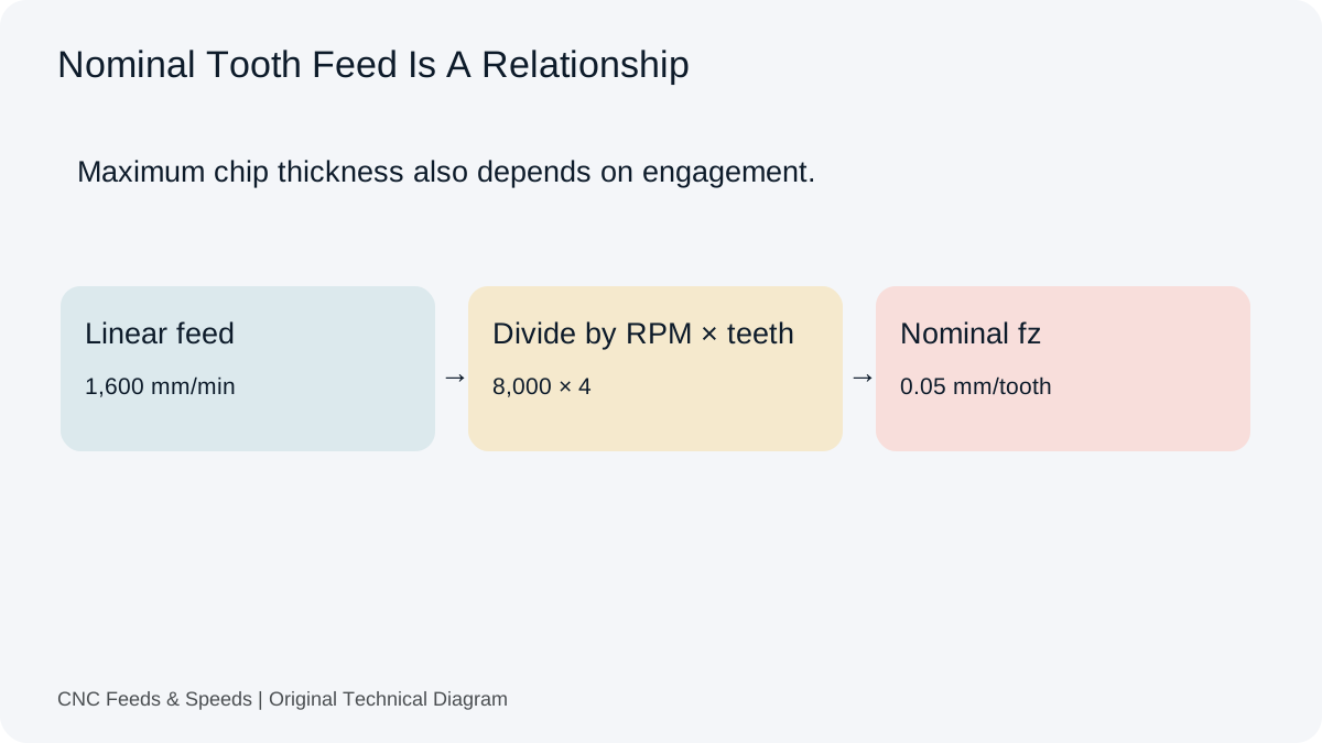
Once RPM is established, milling feed is F = RPM × Z × fz. If the chart gives feed per tooth, use flute count and spindle speed. If it gives feed per revolution, use F = RPM × f/rev. Keep those conventions separate.
Check diameter bands and interpolation
Tables are often grouped into diameter ranges. A 6 mm tool may not share the same starting data as a 20 mm cutter, even when both are carbide and used in the same alloy. Follow the chart’s method for moving between sizes instead of treating the nearest row as exact.
Look for engagement conditions
Slotting, full-width cutting and low-radial-engagement adaptive milling can require different starting values. If the chart specifies a percentage of diameter or a maximum axial depth, capture those conditions with the cutting speed and chip load. A value without its associated engagement can be misleading.
Cross-check with the machine
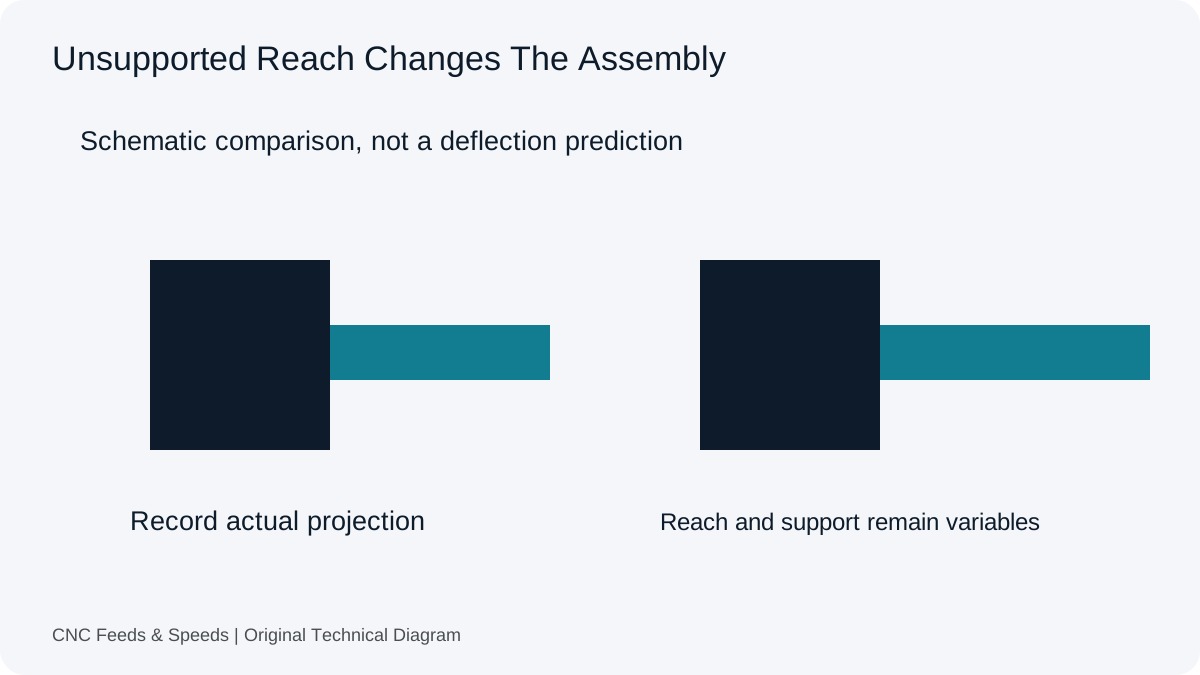
After calculating RPM and feed, compare them with the machine spindle and feed limits. Then assess tool stick-out, workholding, spindle power, torque and coolant. The chart cannot see the machine on which the cut will run.
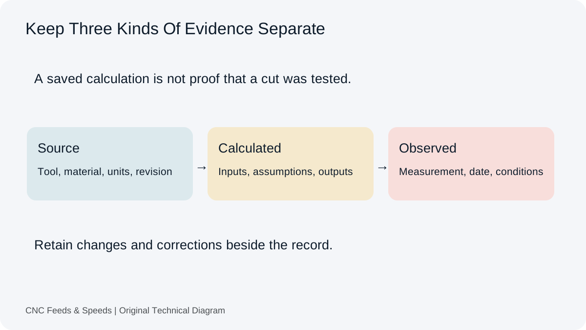
Keep a source record
Save the table name, tool family, material, diameter, row/column used and date accessed with the setup. That makes the calculation auditable later and helps explain why two setup sheets contain different starting values.
Use the result as a starting condition
A first pass should be controlled. Listen for chatter, inspect chip formation, monitor load and check the edge. Once the cut is proven, record the actual conditions rather than replacing the proven value with a generic online table.
Transfer The Whole Condition Into CAM
Begin with an identifiable tool and material condition, rather than a family name alone. Record the tool part number, source units, cutting speed, feed basis and the engagement that accompanies the recommendation. A value quoted for side milling does not describe a full slot merely because both operations use the same diameter.
Axial Depth Of Cut
Axial depth (ap) describes engagement along the cutter axis. It is not the cutter diameter. Check whether the source states this depth in millimetres, inches or a multiple of tool diameter before you enter it.
Radial Width Of Cut
Radial width (ae) describes engagement across the cutter. A 1 mm width on a 10 mm tool is 10% of its diameter. Keep the width and percentage distinct when CAM presents them in different fields.
One Transparent Arithmetic Record
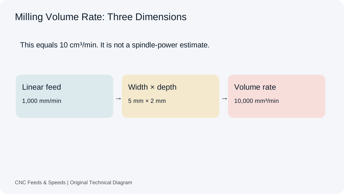
For an illustrative 10 mm cutter at 200 m/min, theoretical speed is about 6,366.198 RPM. Four effective teeth and 0.04 mm/tooth give about 1,018.592 mm/min. At 2 mm radial width and 5 mm axial depth, removal rate is about 10,185.916 mm³/min. These are demonstration inputs, not a material recommendation.
Use the milling workspace to inspect the relationships, then compare each CAM field with the same quantity and unit. Record any machine limit or feed adjustment separately. The chip-load explanation describes why a compensated feed cannot always be treated as an unadjusted feed per tooth.
Frequently asked questions
Can I copy a feed and speed chart directly into the CNC?
Only after confirming the tool, material, operation, units, engagement and machine limits match. Charts are reference inputs, not universal machine commands.
Why do two charts disagree?
They may use different tool geometry, material conditions, assumptions, or test setups. Compare definitions before comparing numbers.
How can a calculator help?
It can verify the arithmetic that connects cutting speed, diameter, RPM, flute count and chip load without replacing the chart itself.
Applications And Related Calculation Workflows
From A Cutting Chart To A Reproducible Calculation
Record the tool identifier, material condition, operation and units before transferring numbers from a chart. Keep source cutting speed separate from RPM and source tooth feed separate from linear feed. Use the main calculation workspace only after those definitions are clear. A repeatable calculation records where the values came from as well as what they produce.
For a primary example of defined machining symbols, use Sandvik Coromant’s milling reference. For named stock materials, the material reference library links producer and supplier sources.
Help Improve This Resource
Request A Tool
Describe the calculation your workflow needs, the inputs you already have and the output you want to check. Include units and an example without confidential job details.
Request A ToolReport An Error
Share this page address, the entered values and the result you expected. Include the source of your comparison so the formula, units and explanation can be investigated.
Report An ErrorCNC Feeds & Speeds Editorial Desk
The site brings calculation tools and machining references into one workspace. Use the editorial and site information to understand its purpose and limitations. Send corrections with a reproducible example through the error report form.