Calculate milling RPM and feed, review end mill engagement and keep source data with the setup.
Milling RPM And Feed
Use the cutter diameter, effective flute count and source cutting data to work from surface speed to spindle RPM, then from tooth feed to linear feed. The basic panel performs that calculation. The advanced panel adds width, depth and travel so you can inspect the entered condition in more detail.
Used For
Plan or audit end mill speed and feed for a specified milling operation.
Enter the values you know. The result is calculated in your browser.
Calculation only. Verify toolmaker data, material grade, engagement, machine limits, workholding and actual cutting conditions before production.
Milling Engagement And Machine Limits
Use the fuller calculation when additional process and machine variables matter.
Feed Speed
Enter the values you know. The result is calculated in your browser.
Calculation only. Verify toolmaker data, material grade, engagement, machine limits, workholding and actual cutting conditions before production.
Milling Quick Tools
Use these checks when one part of a milling condition changes. Inspect tooth feed from an existing program, estimate removed volume at a known engagement, or calculate steady-feed travel time. Select source data for the actual cutter before interpreting a result.
Check Programmed Tooth Feed
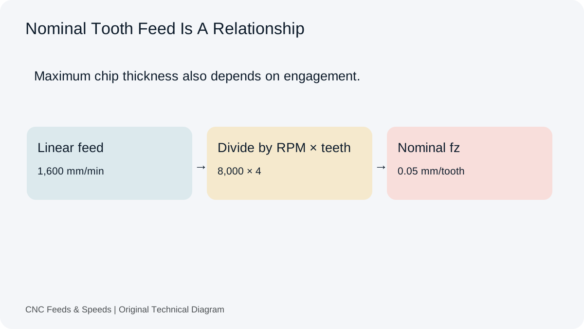
Find nominal feed per tooth from actual RPM, effective teeth and linear feed. Use this reverse calculation after a speed or feed adjustment. It does not correct for runout or radial chip thinning.
Open Chip Load Check
Feed per tooth = linear feed ÷ (RPM × effective teeth). Example: 1,600 ÷ (8,000 × 4) = 0.05 mm/tooth.
Milling Tooth Feed Check
Enter the values you know. The result is calculated in your browser.
Calculation only. Verify toolmaker data, material grade, engagement, machine limits, workholding and actual cutting conditions before production.
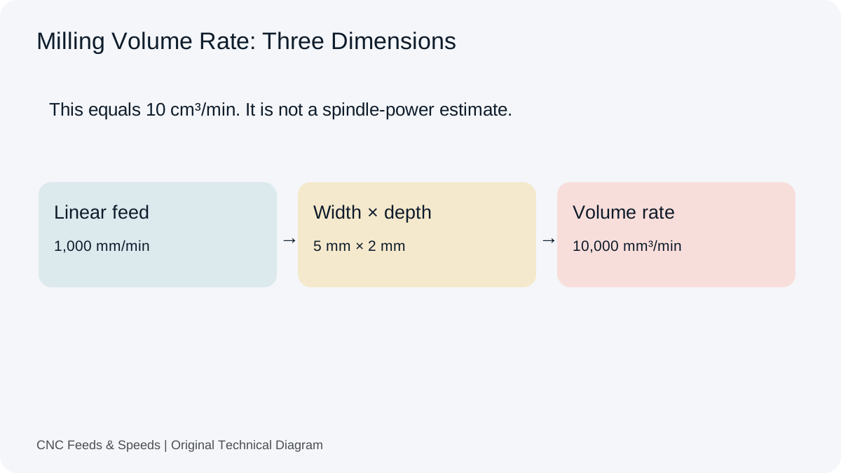
Compare removed volume using a known feed, radial width and axial depth. This check assumes a constant removed cross-section. It does not estimate spindle power or stability during a changing toolpath.
Find the time for a stated cutting distance at a constant linear feed. Use it for a defined travel segment. Keep entries, tool changes, rapid moves and controller slowdowns separate from this estimate.
Open Cutting Time Check
Time = cutting distance ÷ linear feed per minute. Example: 500 mm ÷ 1,000 mm/min = 0.5 minute.
Milling Travel Time
Enter the values you know. The result is calculated in your browser.
Calculation only. Verify toolmaker data, material grade, engagement, machine limits, workholding and actual cutting conditions before production.
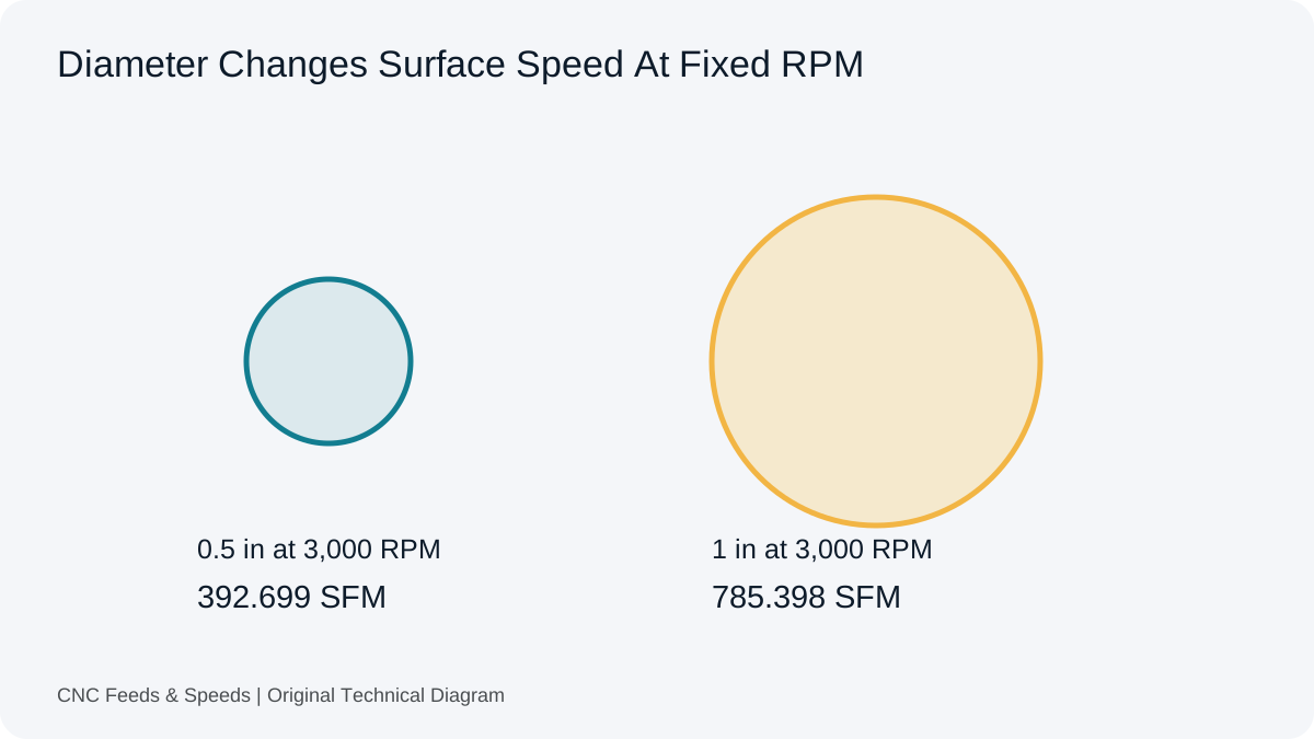
Use the cutter diameter and actual RPM to recover the surface speed at the machine setting. This is useful after a spindle limit or manual speed change. Compare that result with the original tool reference before retaining the source condition.
Open Surface Speed Check
Metric Vc = π × diameter × RPM ÷ 1000. Example: 10 mm at 6,000 RPM gives 188.50 m/min.
Milling Surface Speed At Actual RPM
Enter the values you know. The result is calculated in your browser.
Calculation only. Verify toolmaker data, material grade, engagement, machine limits, workholding and actual cutting conditions before production.
Calculate travel for a defined interval at constant feed. Use it to compare a simple move with a recorded cutting interval. Total runtime includes other events, so it cannot be converted into distance through this model without those distinctions.
Open Travel Length Check
Length = feed per minute × time in minutes. Example: 500 mm/min × 2 min = 1,000 mm.
Constant-Feed Milling Travel
Enter the values you know. The result is calculated in your browser.
Calculation only. Verify toolmaker data, material grade, engagement, machine limits, workholding and actual cutting conditions before production.
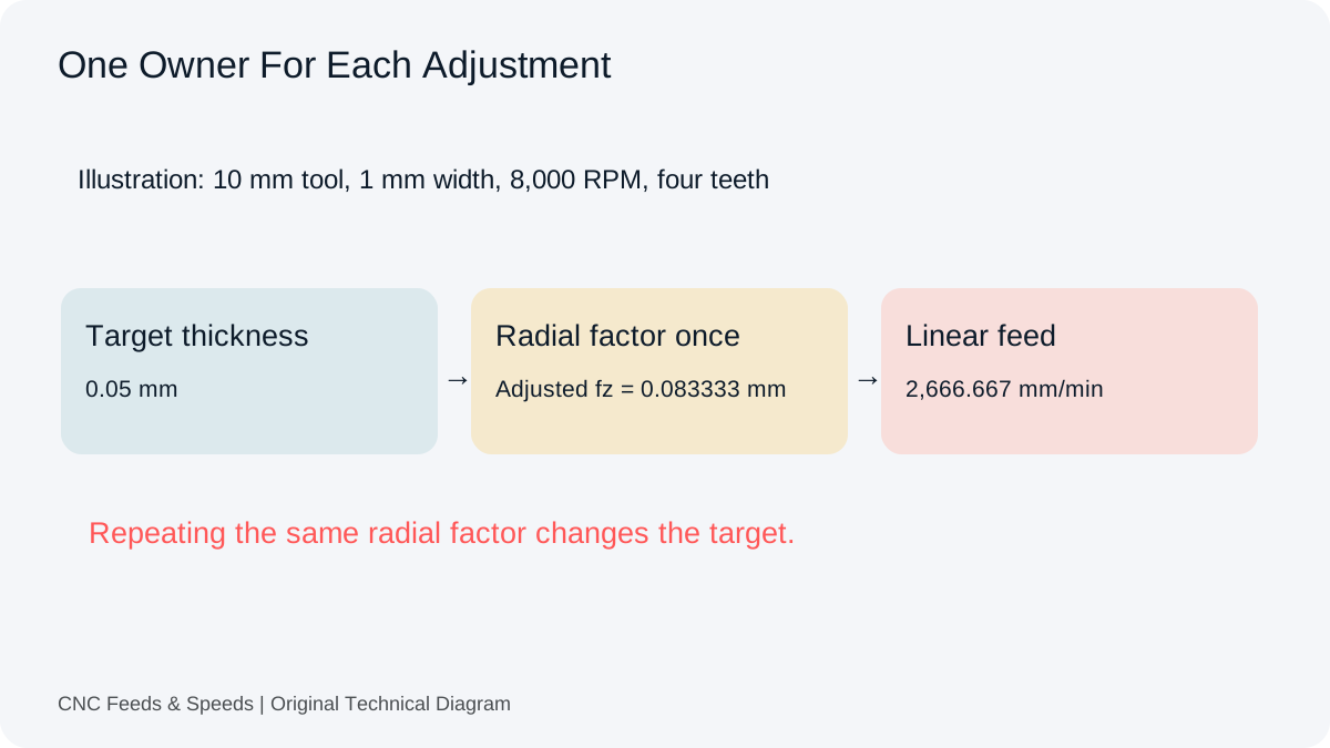
Set a target maximum chip thickness for cylindrical 90 degree side milling. Compare the adjusted tooth feed with actual RPM and effective teeth. Check whether your source or CAM already includes this adjustment.
Open Radial Chip Thinning
For 0 < ae < D/2: factor = D ÷ (2 × √(ae × (D − ae))). At half diameter and above, factor = 1. Example: D 10 mm, ae 1 mm and target 0.05 mm give adjusted tooth feed 0.083333 mm.
Radial Chip Thinning
Enter the values you know. The result is calculated in your browser.
Calculation only. Verify toolmaker data, material grade, engagement, machine limits, workholding and actual cutting conditions before production.
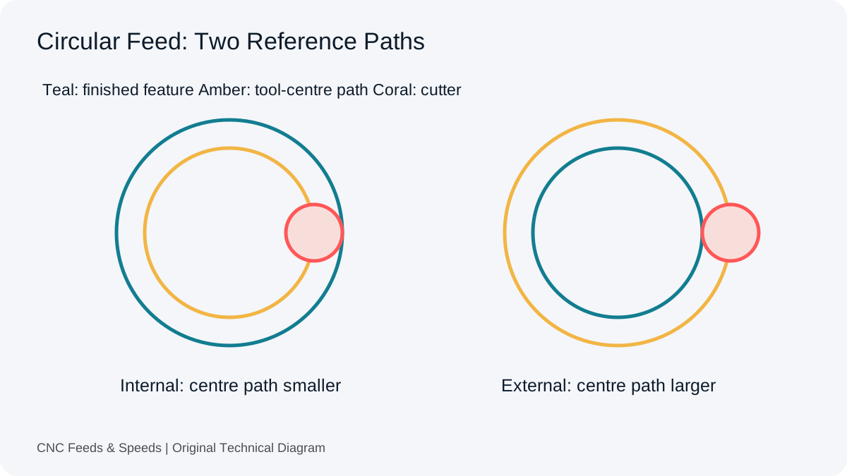
Convert a peripheral reference feed into the final tool-center command for a circular bore. Enter finished feature and cutter diameters in the same units. This planar calculation excludes helical motion and automatic CAM compensation.
Open Internal Circular Feed
Center feed = reference feed × (finished bore diameter − cutter diameter) ÷ finished bore diameter. Example: 40 mm bore, 10 mm cutter and 1,000 mm/min reference give 750 mm/min.
Internal Circular Feed
Enter the values you know. The result is calculated in your browser.
Calculation only. Verify toolmaker data, material grade, engagement, machine limits, workholding and actual cutting conditions before production.
Find the tool-center feed for planar circular milling around a finished boss. Keep peripheral feed separate from the resulting command. A factor above one does not override machine, tooling or workholding limits.
Open External Circular Feed
Center feed = reference feed × (finished boss diameter + cutter diameter) ÷ finished boss diameter. Example: 40 mm boss, 10 mm cutter and 1,000 mm/min reference give 1,250 mm/min.
External Circular Feed
Enter the values you know. The result is calculated in your browser.
Calculation only. Verify toolmaker data, material grade, engagement, machine limits, workholding and actual cutting conditions before production.
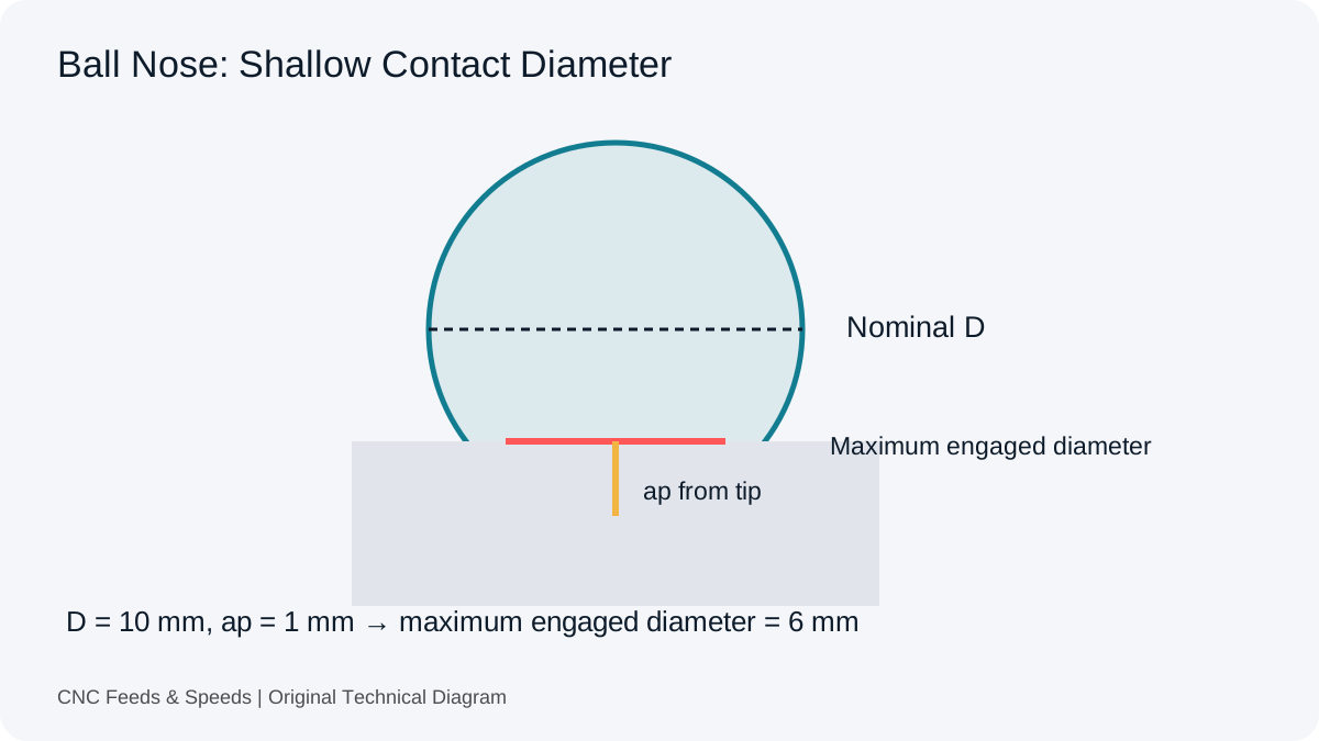
Find maximum engaged diameter for an untilted ball nose on a horizontal surface. Compare requested and capped RPM at that diameter. This model excludes inclined contact, tilt, scallop height and surface-finish predictions.
Open Ball Nose Effective Diameter
Effective diameter = 2 × √(ap × (D − ap)), with depth ap measured from the tip and no greater than D/2. Example: D 10 mm and ap 1 mm give 6 mm. The ball tip still has zero rotational surface speed.
Ball Nose Effective Diameter
Enter the values you know. The result is calculated in your browser.
Calculation only. Verify toolmaker data, material grade, engagement, machine limits, workholding and actual cutting conditions before production.
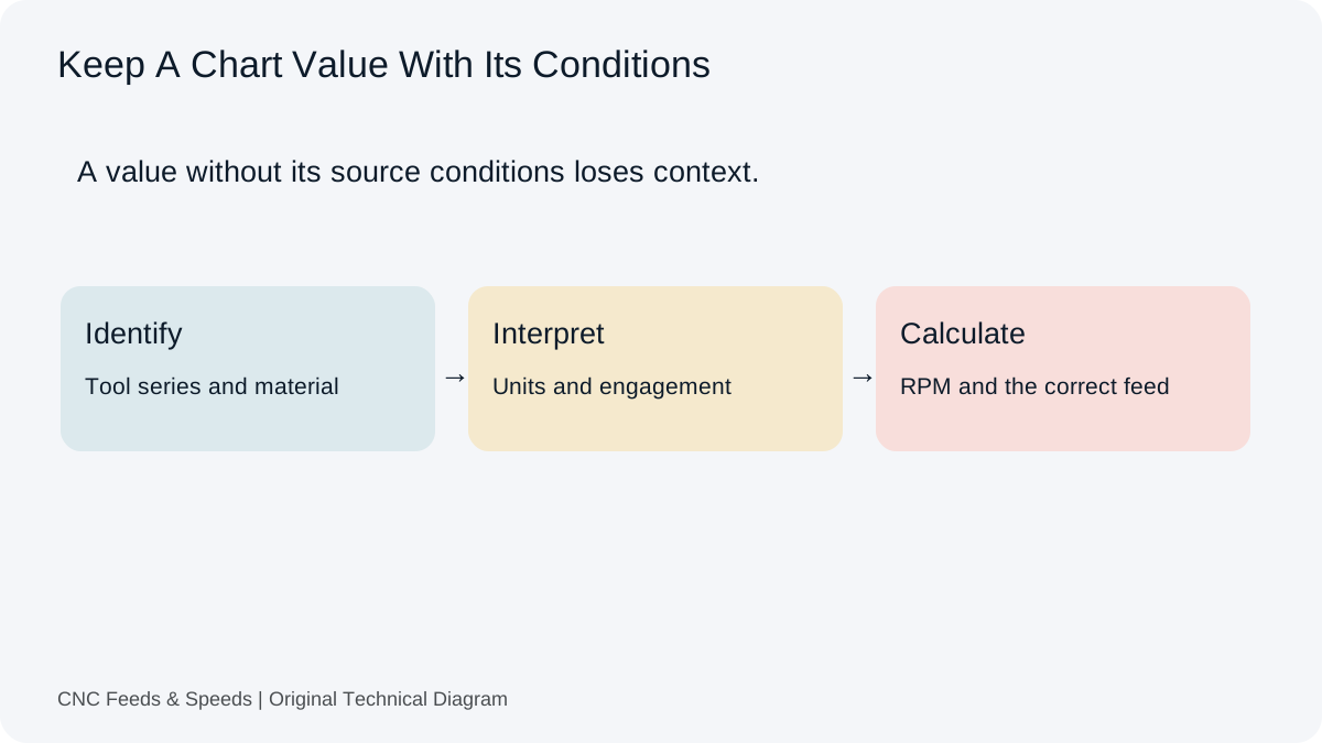
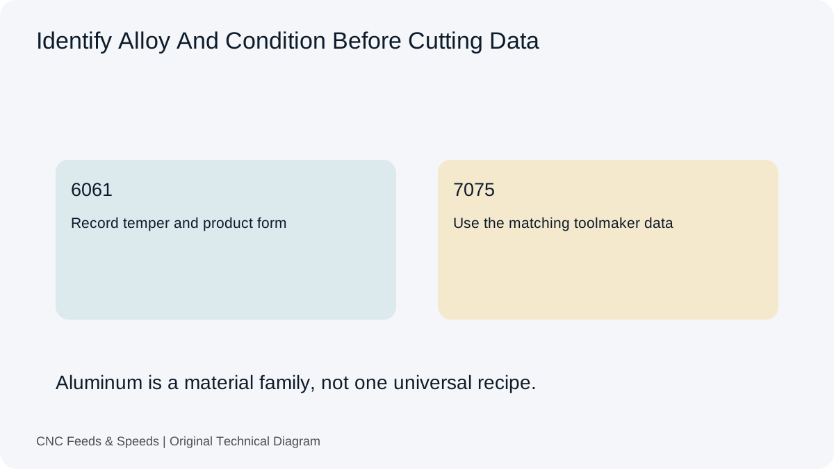
A milling speed and feed calculation needs more than a material name. Record the cutter series, cutting diameter, effective teeth and source tooth feed for the actual cut. Slotting, side milling and a finishing pass can share the same equation while using different inputs. Keep the toolmaker engagement conditions beside the numbers you enter.
From Cutting Data To A Feed Command
Select the unit mode. Metric speed uses m/min with diameter in mm; imperial speed uses SFM with diameter in inches.
Enter the source cutting speed and cutting diameter. Add the effective teeth and feed per tooth from the same tool reference.
Calculate RPM and feed. If the machine cannot reach that RPM, use actual RPM in the feed rate calculator before choosing a programmed feed.
Use the advanced panel to inspect engagement, travel and the spindle limit. If the calculated RPM exceeds that limit, feed and material removal rate use the capped RPM. Ideal cutting time uses the resulting feed and entered travel; it still excludes approach, retracts, tool changes and other cycle events.
End Mill Speed And Feed Example
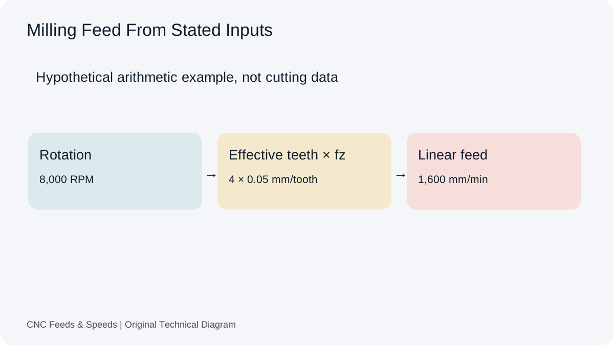
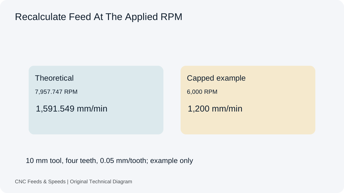
Assume a tooling source supplies 250 m/min and 0.05 mm/tooth for the chosen application. A 10 mm cutter gives 1000 × 250 ÷ (π × 10) = 7,957.75 RPM. Four effective teeth give 7,957.75 × 4 × 0.05 = 1,591.55 mm/min. These assumed values demonstrate the calculation; they are not an aluminum, steel or general end mill recommendation.
At a 6,000 RPM spindle limit, preserving 0.05 mm/tooth requires 6,000 × 4 × 0.05 = 1,200 mm/min. The resulting surface speed is about 188.5 m/min. Check that changed condition against the tool reference instead of assuming the original cutting speed still applies.
Slotting, Side Milling And Entry Feed
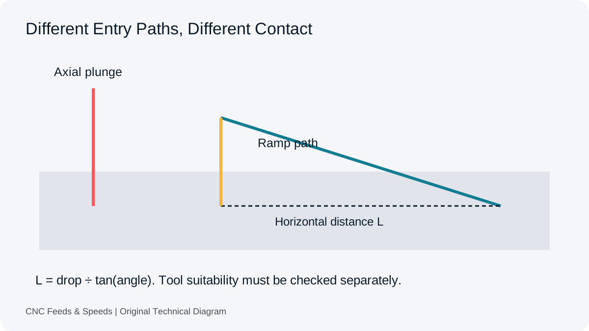
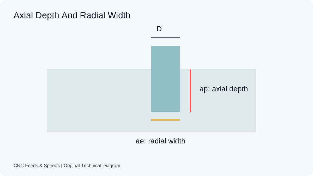
Radial width and axial depth describe how the cutter engages the stock. Use milling material removal rate to compare volume at the selected feed, but keep chip formation and tool load as separate checks. The basic feed equation neither adds chip-thinning compensation nor selects a ramp or plunge feed. Use the entry conditions specified for the tool and motion.
Metric Milling And Supplier References
The metric and imperial calculations describe the same relationships with different length units. A value supplied in mm/tooth must not be entered as inches/tooth. If you use Kennametal tool information, Carbide Depot product data or another supplier reference, retain the exact tool identifier and material condition. This independent site does not connect to those suppliers or select their proprietary cutting data.
Keep An Online Calculation With The Job Record
The workspace runs in the browser. For a file to keep with a setup sheet, use the free milling worksheet on the main calculator page. Record source inputs, theoretical results, final programmed values and any reason for a change. The CSV is a record sheet, not an installed calculator app.
The circular-feed tools output a final tool-center feed for a planar circular path. They do not add a percentage to an already compensated command. Confirm what your CAM and control expect, particularly where cutter compensation or another feed adjustment is active.
Radial chip thinning and ball nose contact address different geometries. The first assumes a cylindrical 90 degree cutting edge; the second restricts contact depth to half the diameter on an untilted tool. Use the accompanying source notes and keep each check separate from material selection or a claim of process stability.
Ball Nose Scallop And Stepover
A ball nose tool can leave a geometric ridge between neighbouring passes even when its effective cutting diameter has been checked. These tools inspect the cross-section of parallel passes on a plane. Keep cusp height separate from a measured roughness specification, and do not use the calculation as an automatic feed adjustment.
Height From A Stepover
Enter ball diameter and parallel pass spacing to find an ideal geometric scallop height. Compare the effect of a different stepover while holding diameter constant. The result describes the circular trace between passes, without tool tilt, surface curvature, wear or machine motion errors.
Open Scallop Height Tool
With radius R and stepover s, height h = R − √(R² − (s ÷ 2)²). A 10 mm ball and 1 mm stepover give approximately 0.025063 mm, or 25.063 µm. The implementation uses an equivalent form that avoids loss of precision at very small stepovers.
Planar Ball Nose Scallop Height
Enter the values you know. The result is calculated in your browser.
Calculation only. Verify toolmaker data, material grade, engagement, machine limits, workholding and actual cutting conditions before production.
Stepover must be positive and no larger than the ball diameter. The geometric height is not Ra or Rz. A curved surface, a tilted tool or nonparallel passes require a model that matches that geometry.
Work backward from a chosen geometric cusp height to the parallel pass spacing for a ball diameter. Review the spacing in length units and as a diameter percentage. Establish the required surface specification separately because this geometric target is not a measured finish guarantee.
Open Stepover Tool
Rearranging the same circular geometry gives s = 2 × √(h × (2R − h)). A 10 mm ball and a 5 µm target cusp give approximately 0.447102 mm of parallel stepover. Enter height in µm for metric mode or µin for imperial mode, as shown beside the field.
Stepover From Planar Cusp Height
Enter the values you know. The result is calculated in your browser.
Calculation only. Verify toolmaker data, material grade, engagement, machine limits, workholding and actual cutting conditions before production.
The target height must be positive and no greater than the ball radius. This bound defines the model; it does not identify a productive or stable machining condition. Confirm the CAM surface, tool orientation and tolerance settings before choosing the final path.
The two tools use the same ideal circle section in opposite directions. Changing the stepover does not establish the cutting speed, tooth feed or contact dynamics. Harvey Performance’s scallop-height explanation gives toolmaker context for the geometry; the compensation guide addresses a separate question about feed adjustments already present in CAM.
Milling Questions
Which Diameter Should I Enter For An End Mill?
Use the cutting diameter required by the toolmaker calculation. Ball nose engagement, tapered tools and other special geometries can require an effective diameter that differs from the nominal shank or catalogue diameter.
Does A Higher Flute Count Always Permit More Feed?
The multiplication gives more feed at the same RPM and tooth feed. Whether the cut can use it depends on the cutter, chip evacuation and engagement. Use the effective teeth and cutting data stated for the actual tool.
Can This Calculator Diagnose Chatter?
No. Read the tool reach and chatter guide for setup checks. The calculator cannot measure runout, holder stiffness or workpiece support.
Help Improve This Resource
Request A Tool
Describe the calculation your workflow needs, the inputs you already have and the output you want to check. Include units and an example without confidential job details.
Share this page address, the entered values and the result you expected. Include the source of your comparison so the formula, units and explanation can be investigated.
The site brings calculation tools and machining references into one workspace. Use the editorial and site information to understand its purpose and limitations. Send corrections with a reproducible example through the error report form.
Related Articles
Continue with the calculation, setup or troubleshooting question closest to your task.
Circular Milling Feed: Tool Centre Versus Cutting Edge
Convert internal and external circular feed with explicit path geometry. Check what CAM already handles before applying another adjustment.