
Feed & Speed Calculator
Calculate spindle RPM and milling feed from your tooling data. Compare the basic result with engagement, machine limits and cutting time.
Open CalculatorChoose a calculation by the variable you need to check.
Find a tool by the result you need: spindle speed, linear feed, nominal tooth feed, surface speed, material removal rate or cutting time. The library separates those relationships so you can check one input chain at a time.
Calculate spindle RPM and milling feed from your tooling data. Compare the basic result with engagement, machine limits and cutting time.
Open CalculatorConvert cutting speed and diameter into spindle RPM. Check the unit system and compare theoretical speed with the available spindle range.
Open CalculatorCheck milling feed from actual RPM, effective flute count and tooth feed. Recalculate when the spindle setting or cutter changes.
Open CalculatorFind nominal feed per tooth from programmed feed and RPM. Use the effective flute count to compare a saved setting with the tooling reference.
Open CalculatorFind surface feet per minute from diameter and RPM. Check the edge speed behind an imperial setup before comparing it with a toolmaker chart.
Open CalculatorCheck the surface speed produced by an existing spindle setting. Relate the result to the cutting diameter and the units in your reference.
Open CalculatorEstimate milling removal volume from feed, width and depth. Keep engagement assumptions visible when comparing two cutting strategies.
Open CalculatorConvert linear feed and RPM into feed per revolution. Check drilling and turning values without confusing them with milling feed per tooth.
Open CalculatorEstimate constant-feed cutting time from distance and programmed feed. Add pass information while keeping non-cutting cycle events separate.
Open CalculatorRelate spindle speed to thread pitch or TPI for synchronized feed. Check the single-start thread assumption before using the result.
Open CalculatorExplore how broad reference inputs affect RPM and feed. Check the stored assumptions before replacing them with tool-specific production data.
Open CalculatorEstimate turning removal rate from surface speed, radial depth and feed per revolution. Review diameter and spindle limits in the advanced tool.
Open CalculatorCalculate travel from feed and cutting time. Add passes and travel allowance while keeping the constant-feed assumption visible.
Open CalculatorUse the main feed and speed calculator when you have both source cutting speed and chip load. Choose spindle speed for a diameter-to-RPM conversion. For drilling and turning, check the feed convention before using a milling feed equation.
Browse machining operations or review formulas and units.
Some setup questions need a geometric or load check after RPM and feed are known. Open the relevant workspace section below to inspect its assumptions, formula and worked example. These tools extend the calculation record without claiming to choose a suitable cutting condition or replace the machine and tooling documentation.
Distinguish cylindrical hole depth from drill tip travel. Check ideal chamfer depth from the diameters and included angle. Keep the tool contact datum and breakthrough clearance separate from the geometric result.
Open Hole GeometryFind the geometric ridge between parallel passes on a plane. Work backward from a chosen cusp height to stepover. Review the model before comparing its output with a measured surface specification.
Open Scallop ToolsCompare the ideal trace left by a conventional circular nose at a stated feed. Inspect the exact height beside a small-feed approximation. Keep tool wear, vibration and measured roughness outside this geometric estimate.
Open Finish GeometryConnect removal volume to an estimate of cutting power with supplied force data. Check torque at actual spindle RPM and state the assumed efficiency. Compare capacity with the machine curve at that operating point.
Open Power ToolSeparate radial stock from the change in bore diameter. Check ideal annular volume and RPM at the cutting diameter. Use actual speed and the supplier feed convention for the next linear-feed calculation.
Open Boring ChecksLocate the source context before selecting a generic cutting value. Review the difference between cut taps and forming taps. Keep material identity, tool records and source revisions attached to the final setup.
Open Source DirectoryFor prepared-hole references, open the tap-drill guide. Existing milling quick tools also cover radial chip thinning, circular-feed conversion and effective ball nose diameter. Check what the source data or CAM already compensates before applying another adjustment.
Use feed rate for a milling feed command, chip load to inspect an existing milling command, or feed per revolution for the drilling and turning convention. Use cutting speed to check surface speed from diameter and RPM.
A trade page places the calculation in an operation workflow. An individual calculator isolates a quantity so you can audit one relationship without changing the rest of a setup.
Describe the calculation your workflow needs, the inputs you already have and the output you want to check. Include units and an example without confidential job details.
Request A ToolShare this page address, the entered values and the result you expected. Include the source of your comparison so the formula, units and explanation can be investigated.
Report An ErrorThe site brings calculation tools and machining references into one workspace. Use the editorial and site information to understand its purpose and limitations. Send corrections with a reproducible example through the error report form.
Continue with the calculation, setup or troubleshooting question closest to your task.
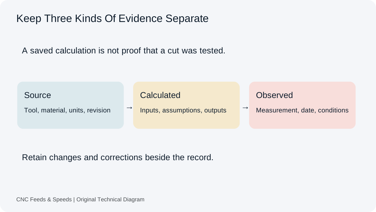
Preserve source data, calculated commands and observed results separately. Use local setup records with clear revisions, units and export limits.
Read Article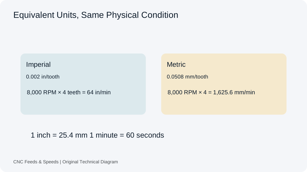
Check length, feed, surface speed, volume and pitch conversions. Follow equivalent metric and imperial examples before transferring a command.
Read Article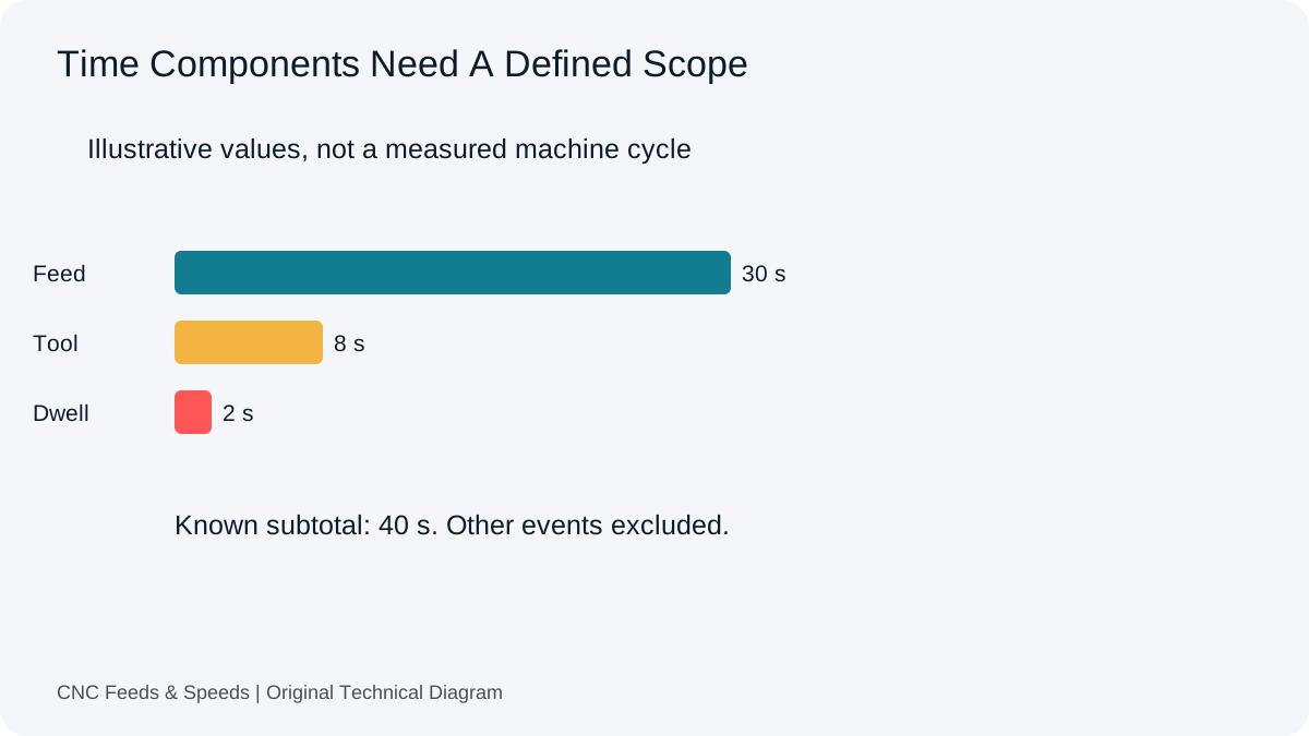
Define the scope behind each time figure. Separate feed travel, machine events, observations and production work before using an estimate.
Read Article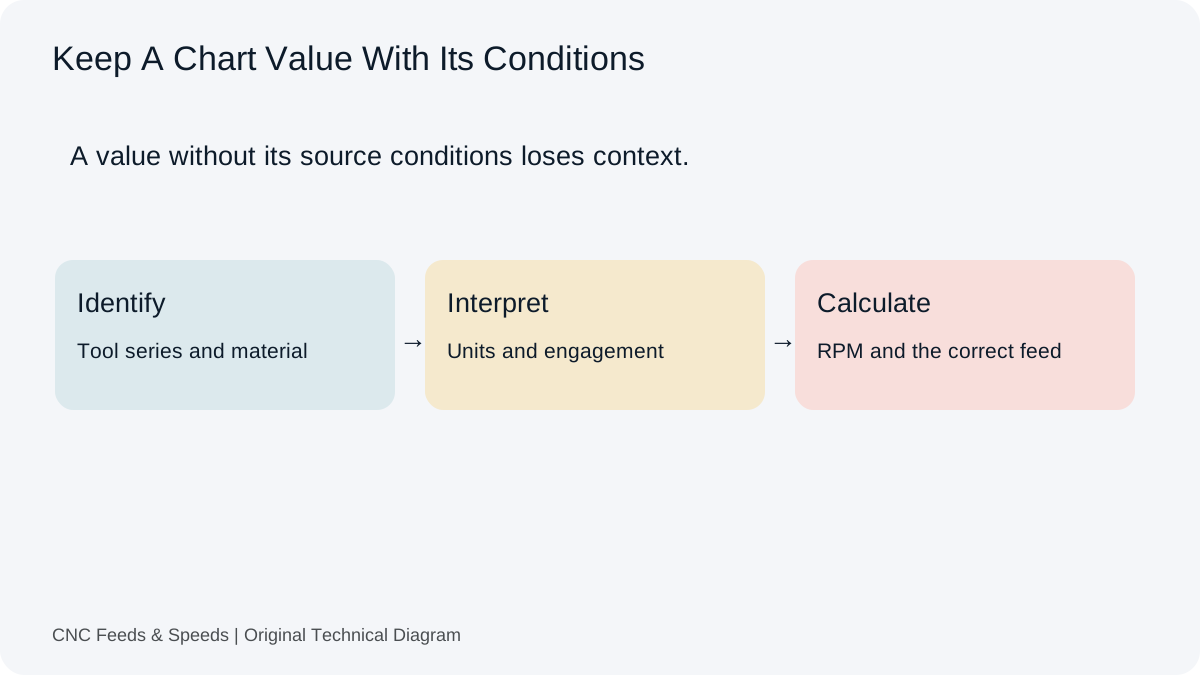
A practical method for interpreting CNC cutting-data charts, matching units, and cross-checking chart values with transparent calculations.
Read Article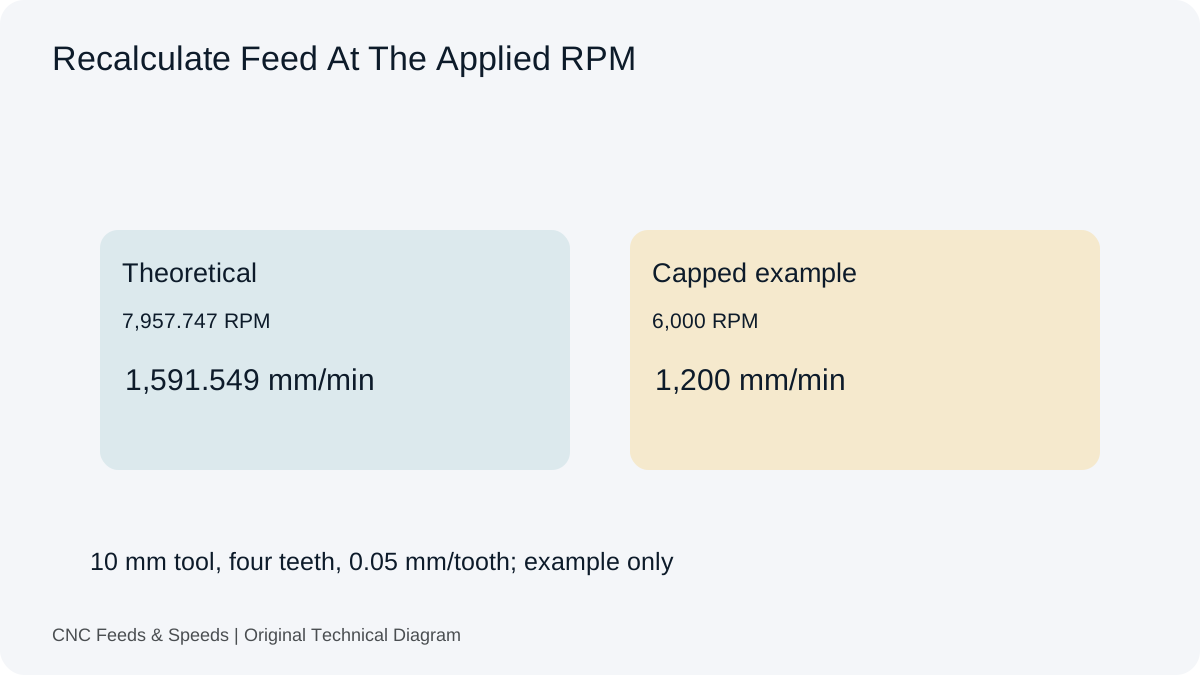
Understand how spindle RPM and programmed feed interact, when feed should scale, and why machine limits change the calculation.
Read Article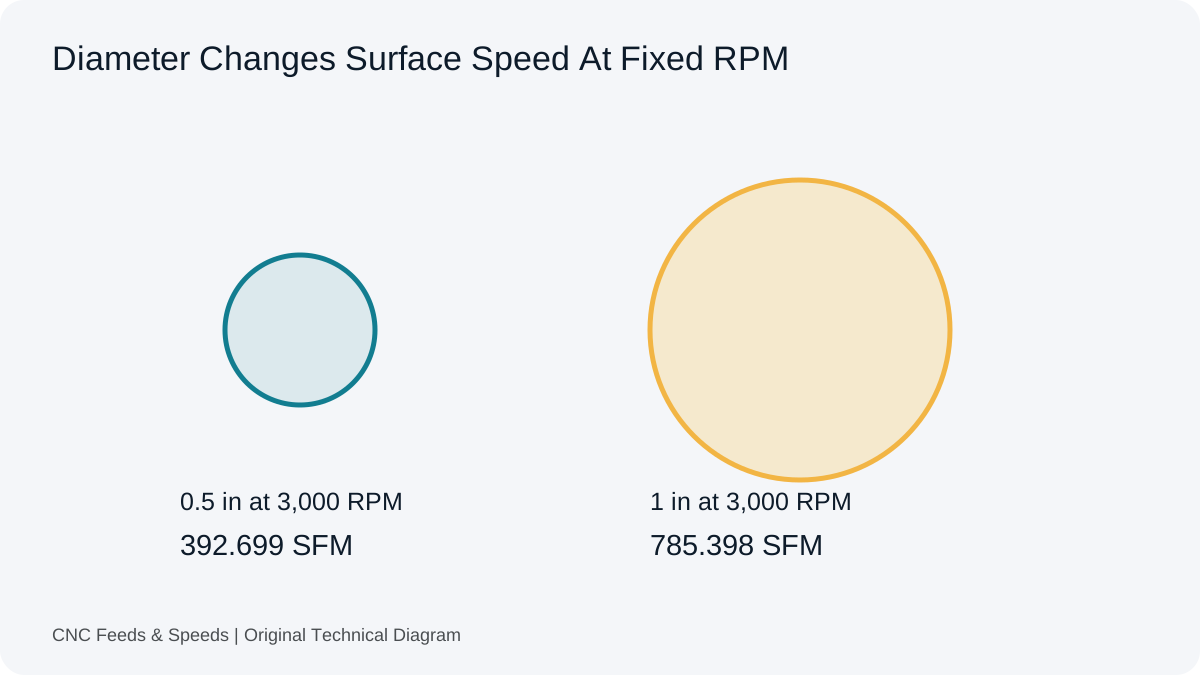
Learn what surface feet per minute means, how it relates to RPM and diameter, and when to use SFM versus metric cutting speed.
Read Article
Separate new cutting travel, re-entry, retracts and dwell. Build a transparent time estimate that respects the actual cycle and controller.
Read Article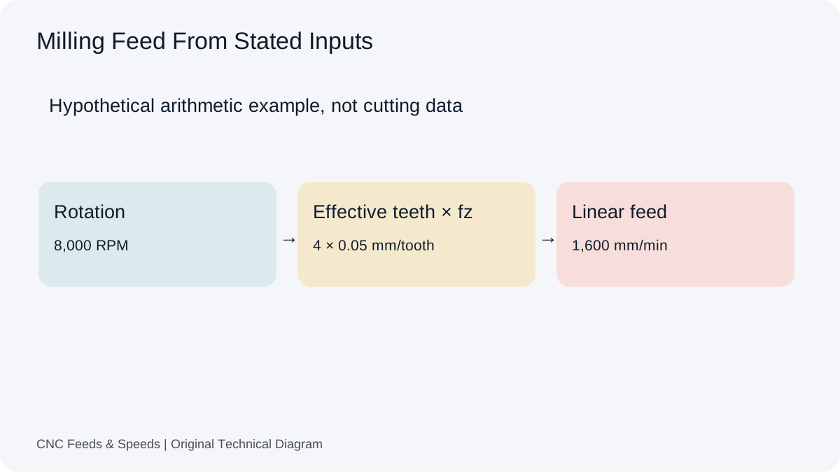
A practical guide to calculating CNC milling feed rate from spindle speed, flute count and chip load, with unit checks and verification steps.
Read Article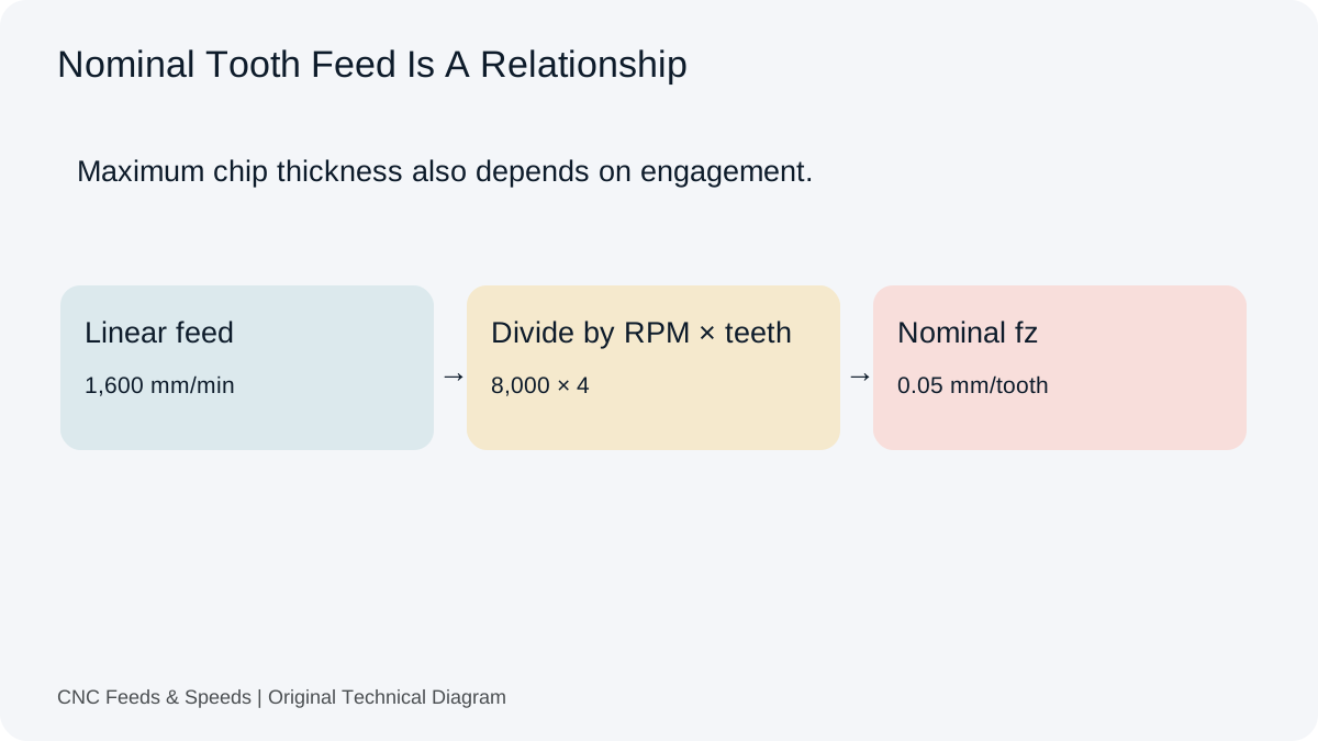
Understand feed per tooth, how chip load is calculated, and how flute count and spindle speed change milling feed.
Read Article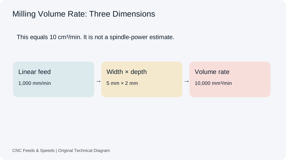
Calculate and interpret material removal rate for CNC milling, including feed, radial engagement and axial depth.
Read Article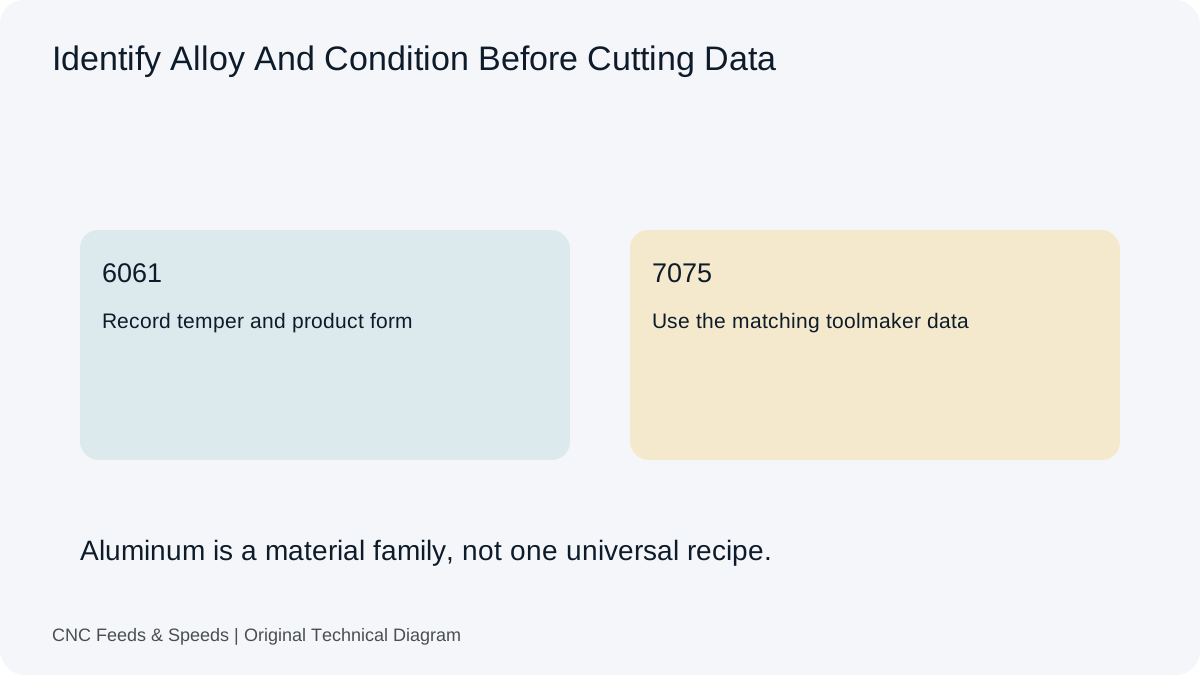
Build an aluminum milling starting point from toolmaker cutting speed and chip load, then verify engagement, chip evacuation and machine limits.
Read Article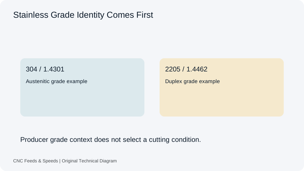
A calculation-first framework for stainless steel machining that emphasizes tool data, chip thickness, rigidity and heat control.
Read Article