Before applying a chip-thinning factor, identify what your starting feed already includes. A supplier recommendation, calculator result and CAM setting can each refer to a different stage of the calculation. The problem is not solved by choosing the largest or most conservative-looking number. It is solved by tracing the quantity from source to final command.
Name The Starting Quantity
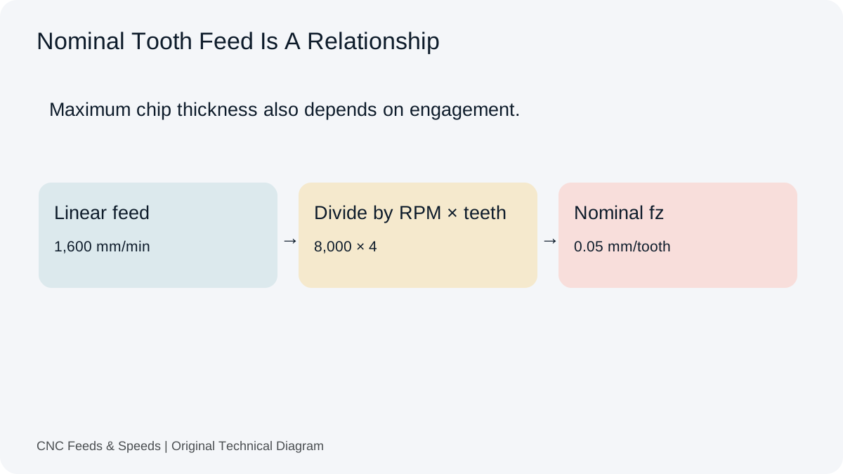
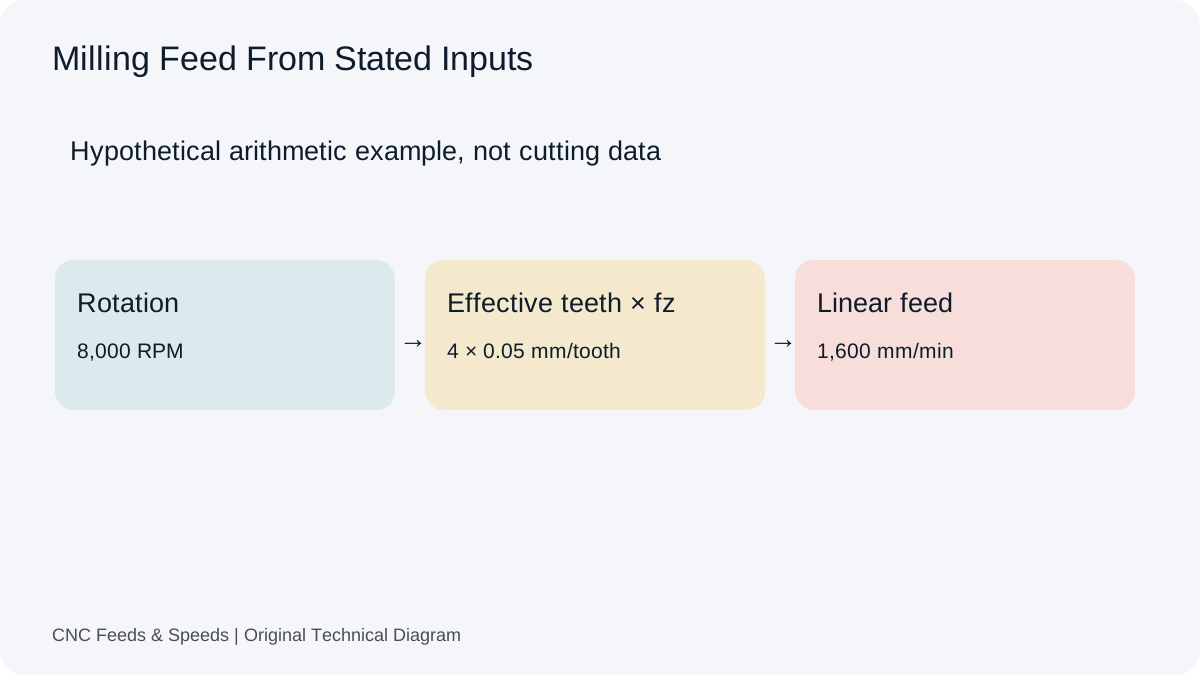
Feed per tooth is a nominal relationship between linear feed, spindle speed and effective teeth. Maximum chip thickness also depends on how the cutting edge engages the work. For a cylindrical cutter at light radial engagement, the maximum chip can be thinner than the nominal tooth feed. A value labelled chip load in a spreadsheet may mean either quantity unless its author has defined the term.
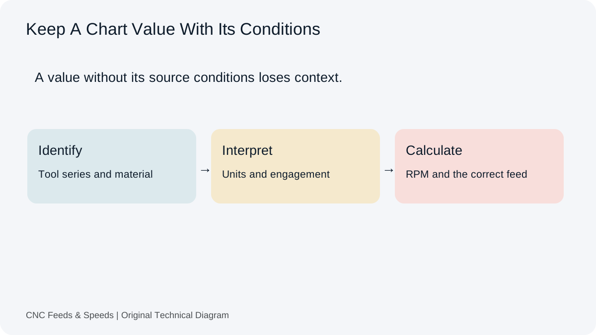
Begin with the distinction between tooth feed and chip thickness. Then inspect the source cutting table. Look for notes about radial engagement, full slotting, recommended stepover or compensated feed. If the table already gives a final feed for a stated engagement, do not reinterpret that number as an uncompensated thickness target without evidence.
A Worked Example Of Repeating The Same Factor
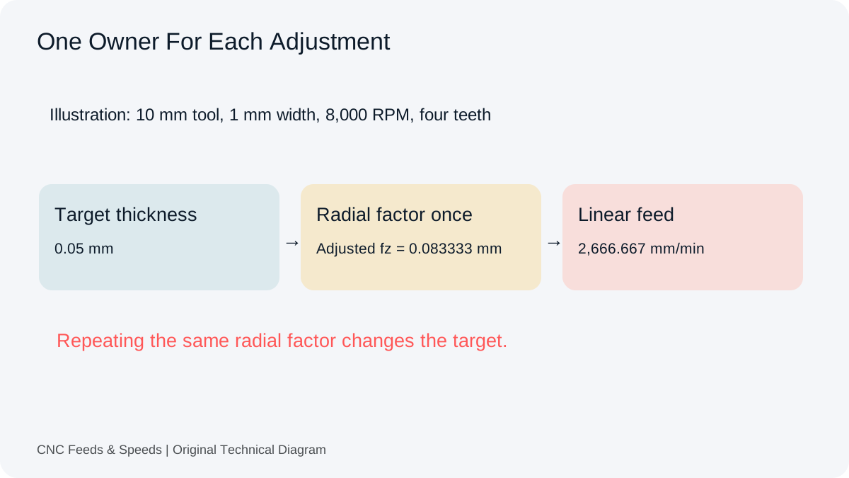
Take an illustrative 10 mm cylindrical cutter with 1 mm radial engagement, 8,000 RPM, four effective teeth and a target maximum chip thickness of 0.05 mm. In the restricted 90 degree side-milling model, the radial factor is 10 ÷ (2 × √(1 × 9)), or 1.666667. Applied once, that gives about 0.083333 mm/tooth and 2,666.667 mm/min. The example demonstrates the geometry, not recommended cutting data.
If the same factor is applied again to the already adjusted tooth feed, the number becomes about 0.138889 mm/tooth. Under the same geometry, that corresponds to approximately 0.083333 mm maximum chip thickness, rather than the original 0.05 mm target. The second identical adjustment has changed the intended condition. A correct formula used twice can therefore produce the wrong result for the stated target.
The radial chip-thinning tool displays the factor, adjusted tooth feed and linear feed separately. That separation helps a reader identify which output they are carrying into another system. It does not tell the calculator whether the starting number was already compensated. That part requires the source definition and the CAM workflow.
Ask Where Each Adjustment Happens
There are several possible owners of a final feed. The tool supplier may publish engagement-specific data. A calculator may convert a target thickness to nominal tooth feed. A CAM operation may alter feed around changing geometry, while the control may impose its own motion limits. These mechanisms are not interchangeable, and their labels may differ between products and versions.
Create a short calculation chain before editing the program. Write the original source quantity and units, the adjustment made outside CAM, the value entered into the operation and the final posted command. Where a setting changes feed dynamically, keep a note of its purpose. If a link in that chain cannot be explained, pause the arithmetic review and inspect the relevant documentation.
Not Every Combination Is Double Compensation
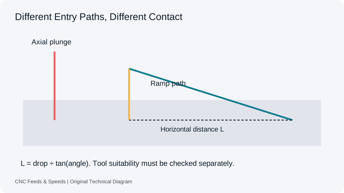
Radial chip thinning, tool-centre circular feed, entry feed and machine velocity limits address different relationships. Two adjustments may legitimately coexist when their meanings and domains are compatible. Calling every combination double compensation would be as misleading as applying every available multiplier. The important question is whether the same physical relationship has been accounted for more than once.
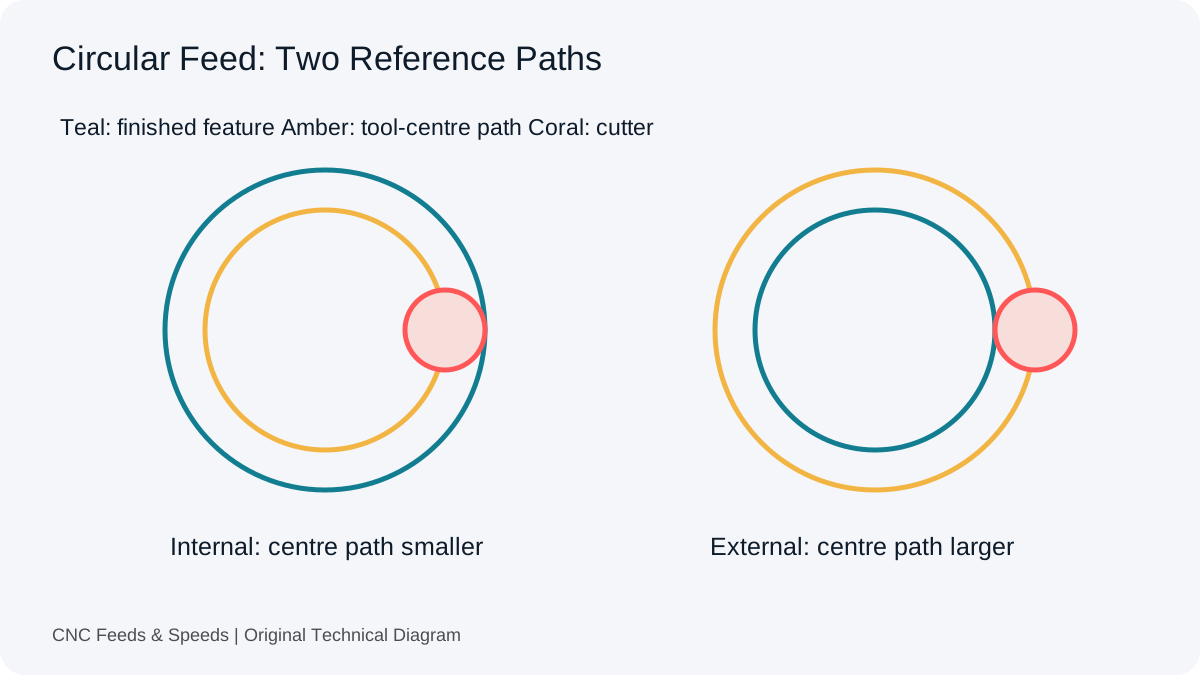
Our circular-feed guide handles a different path-length relationship. Its result is a final tool-centre feed for planar circular motion. It does not calculate radial engagement or replace a CAM strategy. Keep that distinction visible when reviewing a circular pocket, because a repeated factor and a separate valid conversion can otherwise look similar in a list of numbers.
The Half-Diameter Boundary Matters
The simple radial-only model used here returns a factor of one at engagement equal to half the cutter diameter. Above that point, the engaged arc includes the maximum chip-thickness position, so this factor remains one. Extending the low-engagement square-root expression toward a full slot would make the factor rise again. That would be an incorrect continuation of the model.
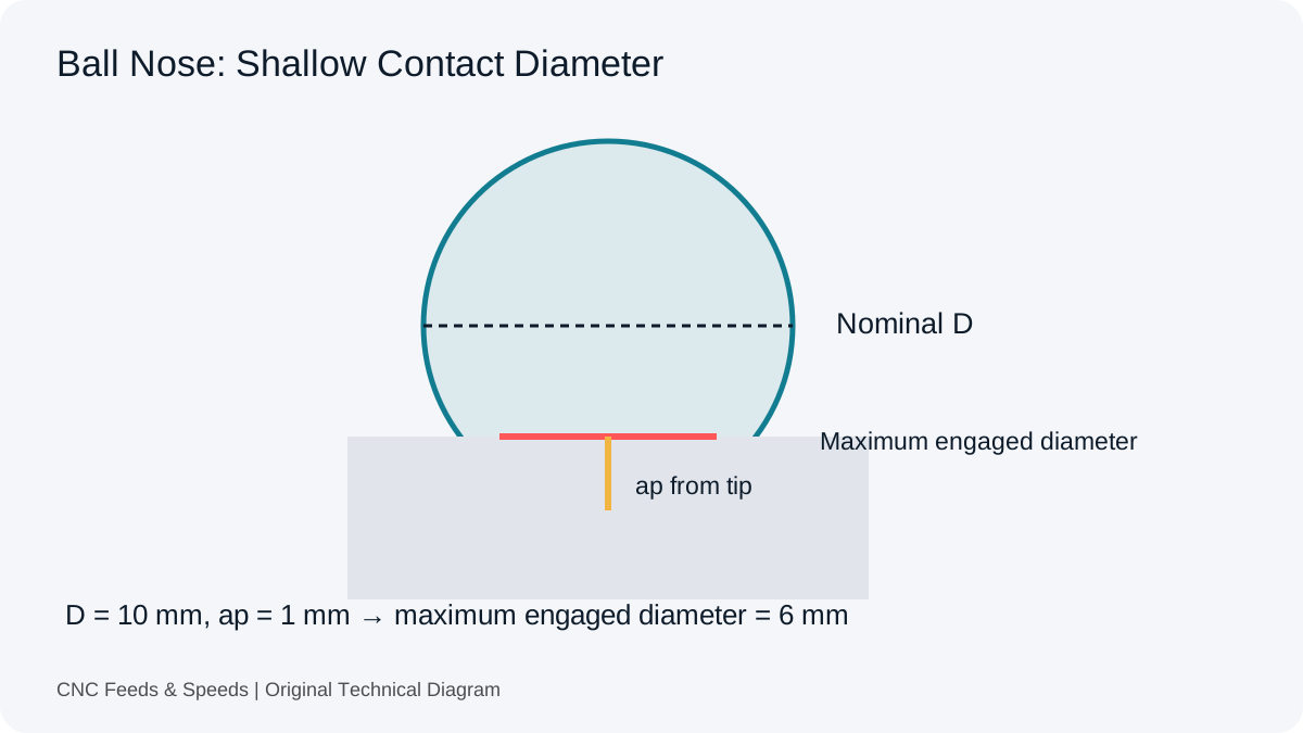
Harvey Performance’s explanation of chip thinning is the technical reference for the engagement distinction. The site’s tool is deliberately limited to cylindrical 90 degree side milling. Ball nose, high-feed inserts, round inserts and changing contact require other geometry. A very large factor near zero engagement is a mathematical warning to inspect limits, not permission to command an arbitrarily high feed.
Why This Deserves A Separate Review
A Practical Machinist discussion about calculator settings includes a direct question about using a calculator’s compensation alongside Mastercam’s setting. It provides the reader problem behind this article. It is a historical discussion, and its replies should not be substituted for current software documentation. We are not claiming that any current CAM product applies an erroneous duplicate adjustment automatically.
When two outputs disagree, compare definitions before concluding that one product is inaccurate. Differences can arise from material assumptions, entering angle, engagement, effective diameter, machine limits or a different meaning of feed. A useful comparison holds those inputs constant and records the exact version and setting. Comparing only the final number leaves too many possible explanations.
Preserve A Traceable Final Feed
After reviewing the assumptions, use the feed-rate calculator to reproduce the nominal RPM × teeth × tooth-feed relationship independently. Write whether the tooth feed is already adjusted. If the resulting number will be entered as a final CAM feed, preserve that fact with the operation so the next programmer does not apply the same radial conversion again.
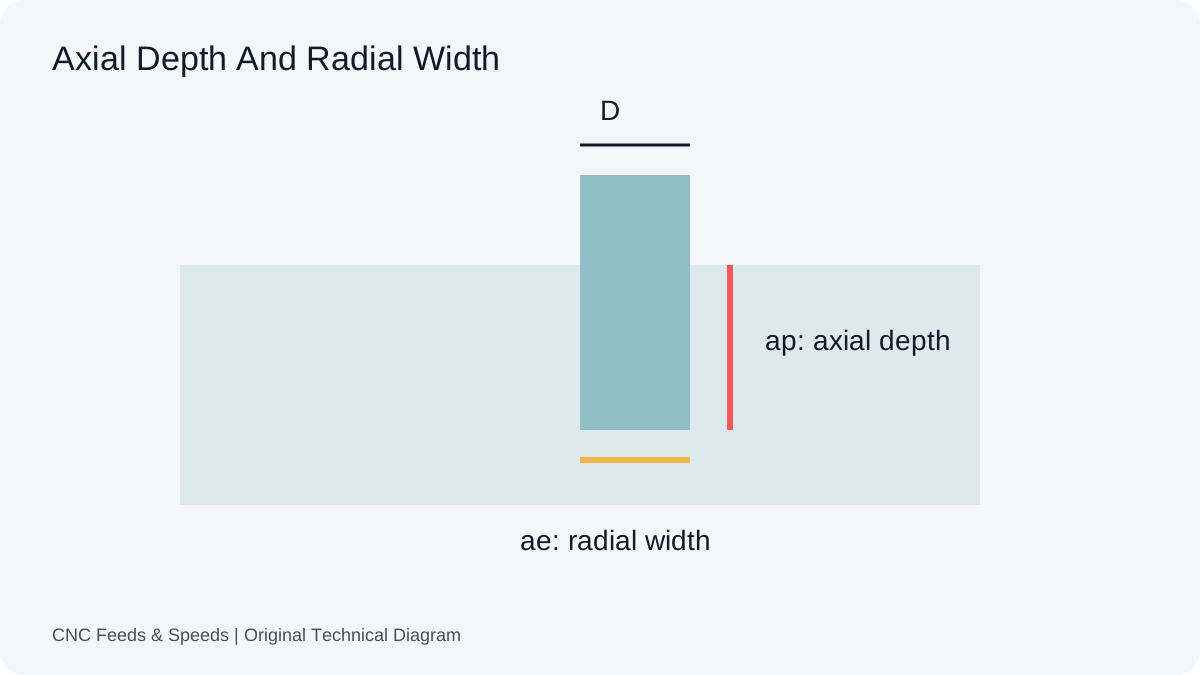
A saved browser record reproduces the calculation, not the machine’s behaviour. Add tool identity, source data, radial width, axial depth and any measured observations to a separate job record. The setup-record workflow keeps proposed conditions, calculated commands and observed results distinct. That distinction prevents a plausible number from becoming an undocumented shop rule.
Compensation Questions
Should I Always Disable A CAM Compensation Setting?
No. Establish what the operation expects and where the adjustment occurs. This article does not provide a universal switch setting for every CAM product.
Can A Toolmaker Feed Already Include Chip Thinning?
It can be engagement-specific. Read the definition and notes instead of assuming every published feed is an unadjusted target thickness.
Does A Factor Of One Prove The Cut Is Suitable?
No. It only describes the radial-only relationship within its domain. Tool capability, engagement, machine limits and workholding remain separate checks.
Help Improve This Resource
Request A Tool
Describe the calculation your workflow needs, the inputs you already have and the output you want to check. Include units and an example without confidential job details.
Request A ToolReport An Error
Share this page address, the entered values and the result you expected. Include the source of your comparison so the formula, units and explanation can be investigated.
Report An ErrorCNC Feeds & Speeds Editorial Desk
The site brings calculation tools and machining references into one workspace. Use the editorial and site information to understand its purpose and limitations. Send corrections with a reproducible example through the error report form.