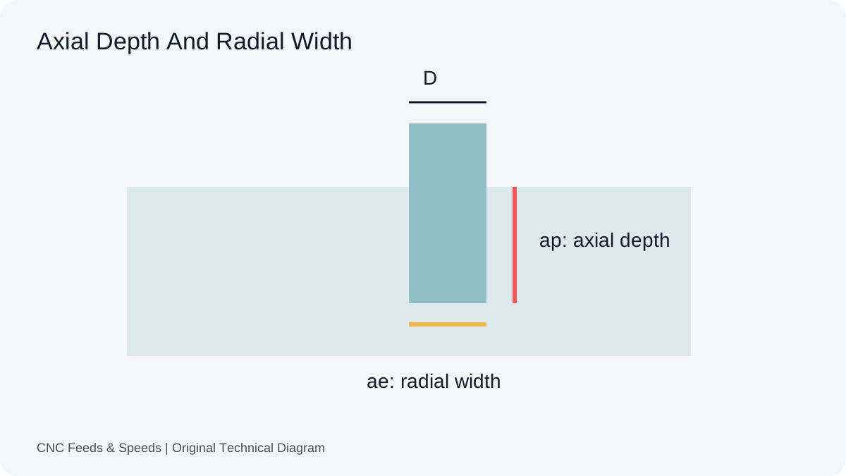
Depth of cut and width of cut describe different directions of engagement. A cutter diameter is neither of them by default. Before entering DOC or WOC into a calculator, identify the tool axis, the amount engaged along it and the amount engaged across it.
Read The Dimension Instead Of Guessing The Acronym
In common milling terminology, axial depth ap describes engagement along the cutter axis, while radial width ae describes engagement across the cutter. Software and supplier wording can vary, so follow the definition attached to the actual field. A drawing of the cut is often more useful than another abbreviated label. Our milling reference connects those dimensions with the rest of the setup.
A Carbide 3D chart discussion includes a reader asking whether DOC means diameter of cutter. That is the specific misunderstanding this diagram addresses. The discussion helps identify the question; the definitions in Sandvik Coromant’s milling reference provide the technical basis for the variables.
Convert A Percentage Into A Dimension
For a 10 mm cylindrical cutter, 10% radial engagement corresponds to 1 mm. Fifty percent corresponds to 5 mm, and a full-width slot corresponds to 10 mm under that simple geometry. Those examples identify a dimension; they do not prescribe a suitable engagement. If CAM asks for a percentage while a calculator asks for millimetres, convert deliberately rather than copy the number unchanged.
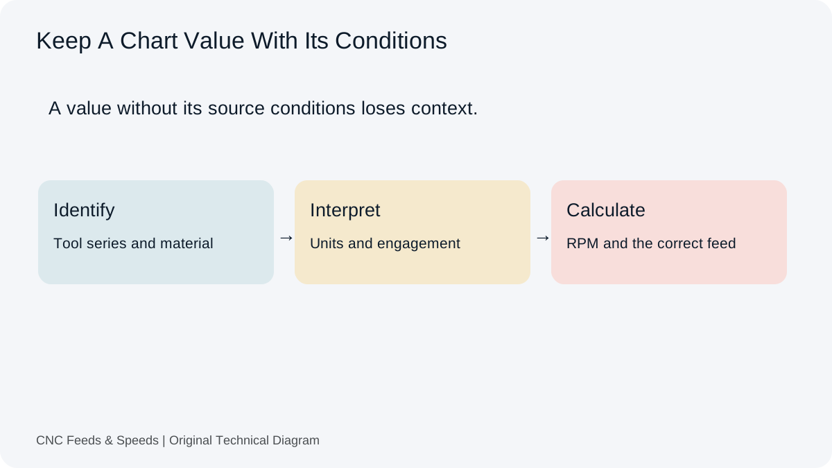
The same caution applies to a source that states axial depth as a multiple of diameter. One diameter of axial engagement for a 10 mm tool means 10 mm, not 1 mm. Preserve the original convention and the converted dimension in the record. The chart-reading guide explains why the source’s operation and engagement notes belong with its feed and speed values.
Equal Removal Rate Does Not Mean Equal Contact
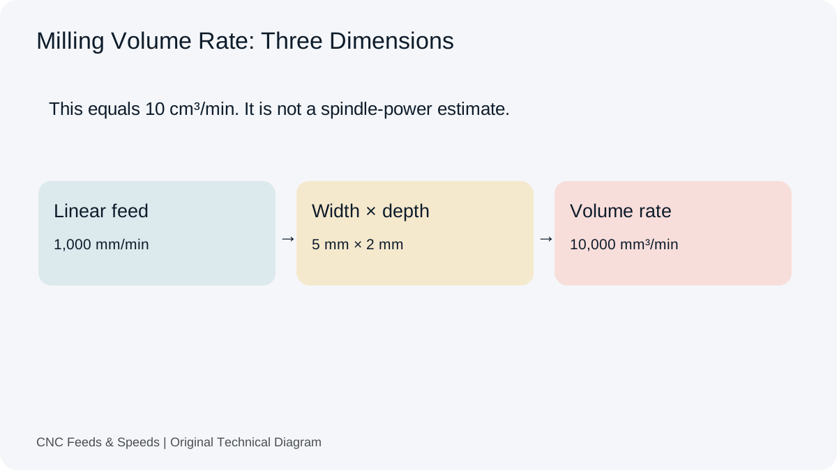
At 2,000 mm/min, a 5 mm axial depth and 1 mm radial width give 10,000 mm³/min. Swapping those dimensions to 1 mm axial depth and 5 mm radial width gives the same simple removal rate. The cutting contact is still different. Chip formation, load direction, evacuation and deflection cannot be assumed identical merely because the volume multiplication gives the same result.
Use the milling MRR calculator to quantify volume for a stated engagement. Keep the comparison separate from tool suitability. The equation contains feed, width and depth, but it does not contain every physical variable that determines whether the cut is stable. An equal MRR is a useful observation, not proof that the two strategies are interchangeable.
Geometry Limits The Interpretation
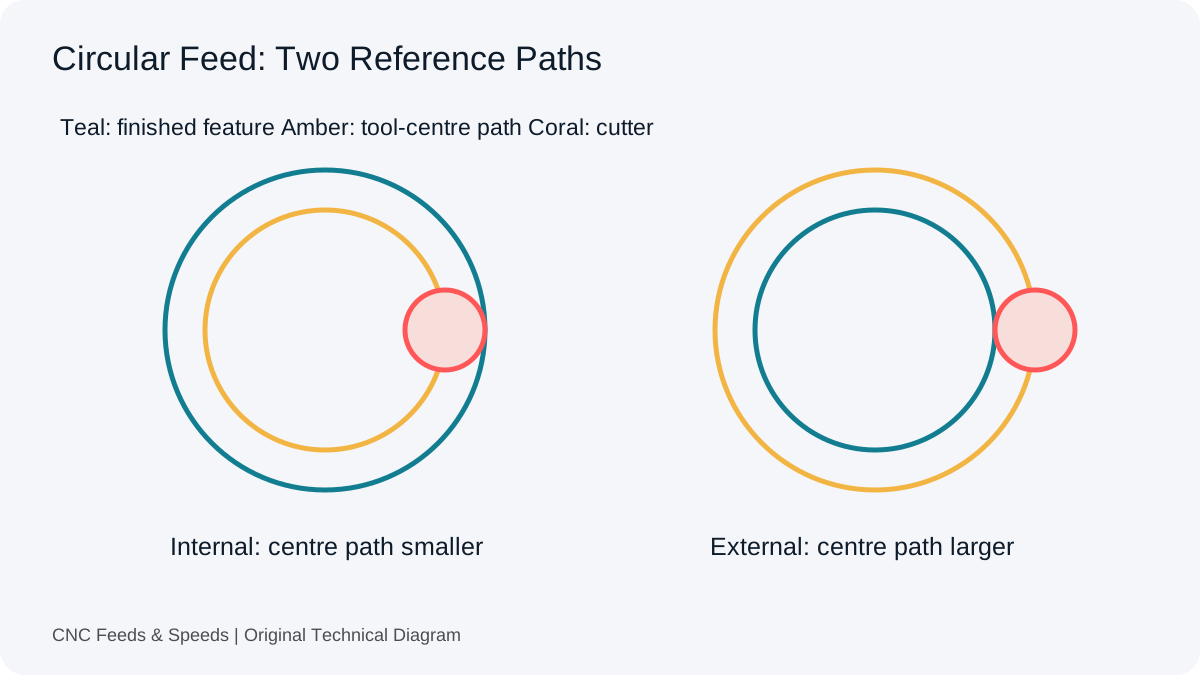
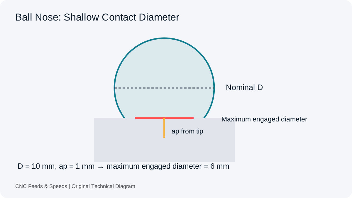
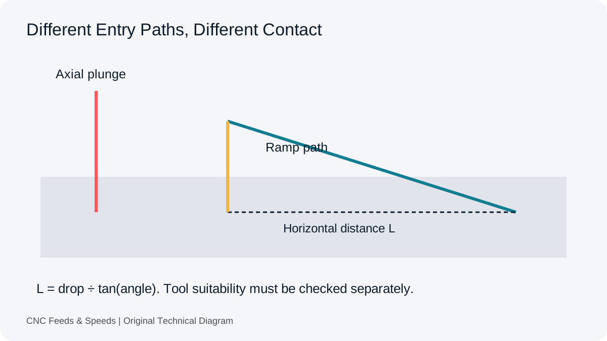
The cylindrical side-milling picture does not describe every cutter. Ball nose contact, round inserts and entering angles change the relevant geometry. A pocket corner can also increase engagement compared with a straight pass. Do not use the static width entered in one calculation as evidence that the entire path sees that same contact.
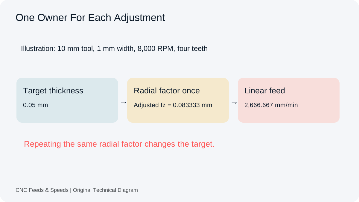
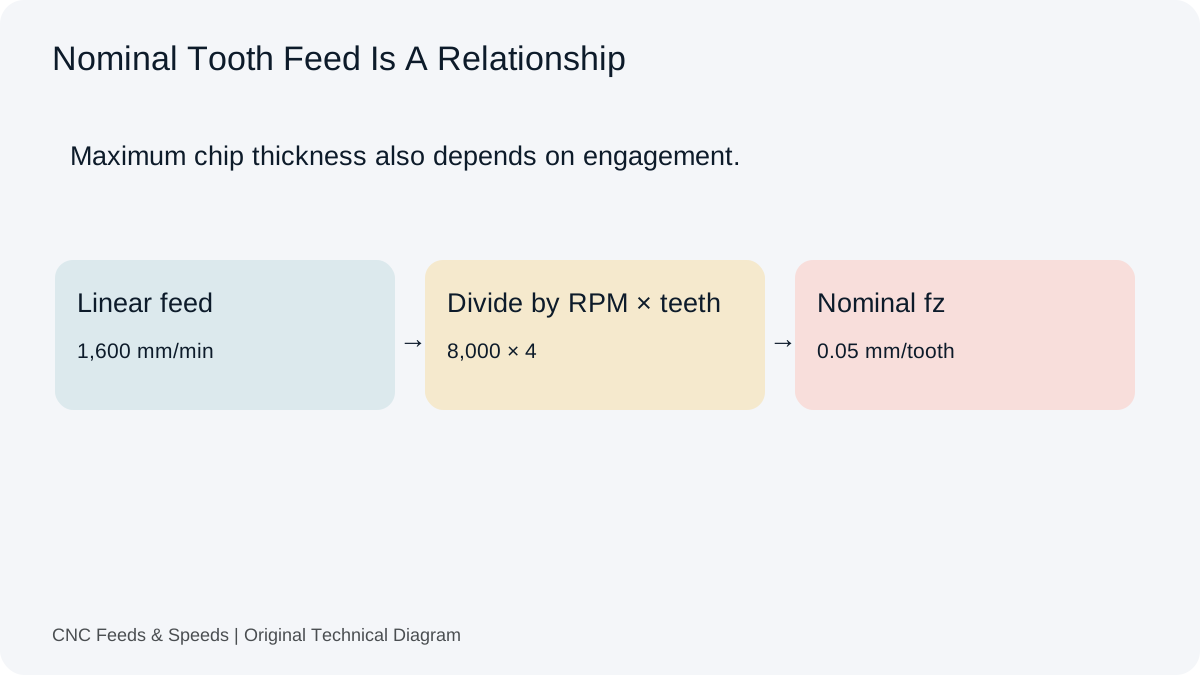
The milling workspace separates basic feed checks from restricted geometry tools. Review each tool’s domain before combining results. If the source or CAM already accounts for chip thinning, an additional radial adjustment may repeat the same relationship rather than improve the condition.
Keep A Visual Check With The Inputs
A useful setup sketch labels cutter diameter, axial depth, radial width, stock surface and travel direction. It need not be a production drawing. Its purpose is to expose whether two people mean the same cut. Keep it with the setup record so a later change in units, tool diameter or operation does not strip the numbers of their meaning.
Engagement Questions
Is DOC The Cutter Diameter?
No. Identify the actual depth dimension described by the source. Cutter diameter is a separate input.
Does The Same MRR Mean The Same Tool Load?
No. Different engagement geometries can produce the same simplified volume rate while behaving differently in the cut.
Can I Copy A Percentage Into A Millimetre Field?
Convert it using the stated reference diameter first. A percentage and a physical dimension are not interchangeable numbers.
Help Improve This Resource
Request A Tool
Describe the calculation your workflow needs, the inputs you already have and the output you want to check. Include units and an example without confidential job details.
Request A ToolReport An Error
Share this page address, the entered values and the result you expected. Include the source of your comparison so the formula, units and explanation can be investigated.
Report An ErrorCNC Feeds & Speeds Editorial Desk
The site brings calculation tools and machining references into one workspace. Use the editorial and site information to understand its purpose and limitations. Send corrections with a reproducible example through the error report form.