A router spindle can have plenty of maximum RPM and still be poorly matched to a drilling operation that needs a much lower usable speed. Lowering the command below the documented operating range is not the same as obtaining a suitable drilling condition. Check the machine range, drill specification and achieved surface speed before treating feed adjustment as the answer.
Start With The Actual Operating Range
Maximum spindle speed is usually easy to find. The minimum useful speed under the intended load may require a closer reading of the machine and spindle documentation. A control can accept a low command while the spindle lacks the required torque or cooling in that condition. The displayed RPM, requested RPM and usable operating range should therefore be treated as separate facts until the machine documentation establishes their relationship.
A Carbide 3D discussion about Nomad drilling shows this difficulty. The user describes drilling trouble and uncertainty about low spindle speed; a manufacturer representative distinguishes requested rotation from useful cutting capability. The historical machine-specific exchange illustrates the question. Its speed range should not be copied as a specification for another machine or a later revision.
Calculate What The Machine Would Actually Do
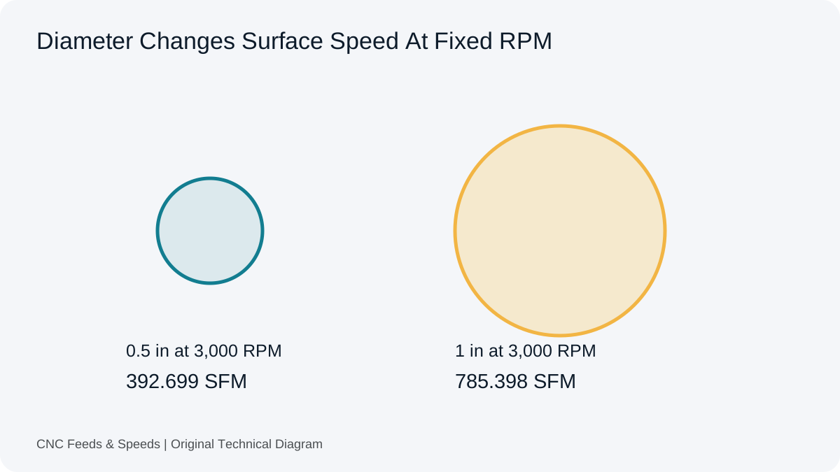
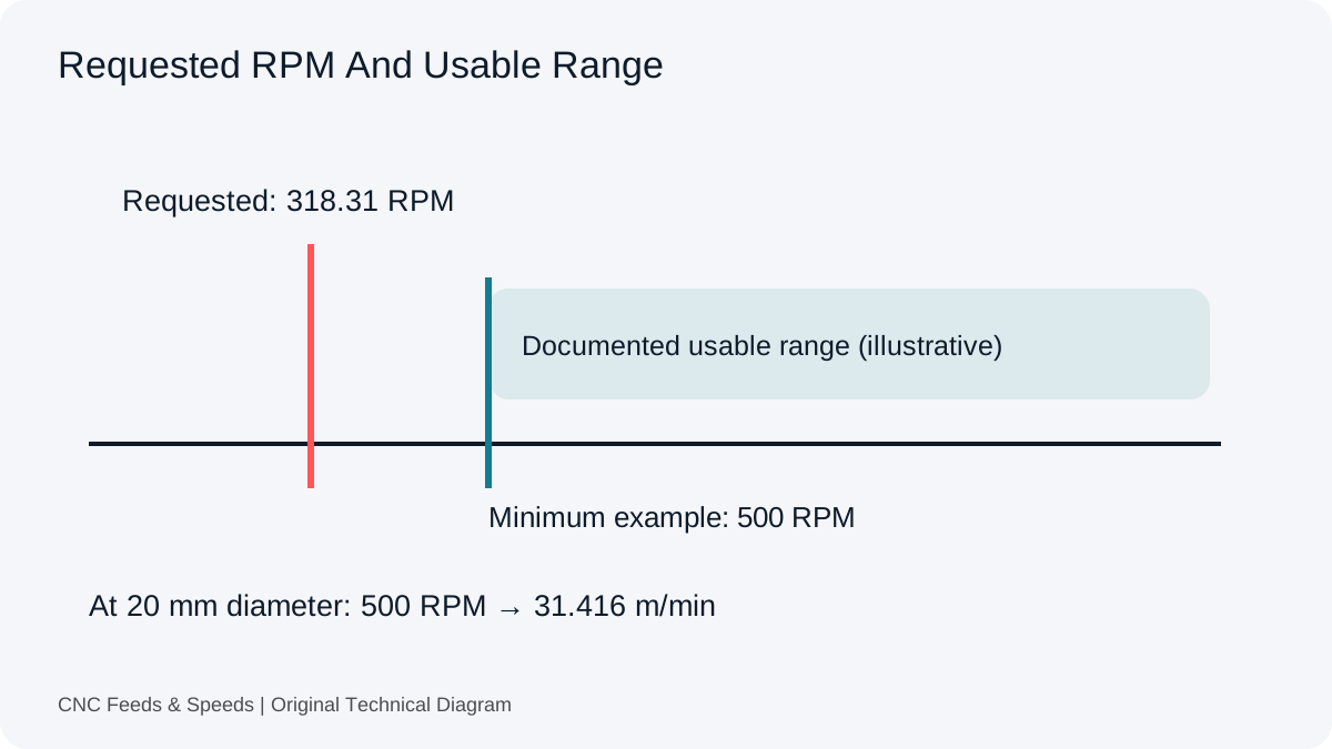
For a hypothetical 20 mm drill and a requested cutting speed of 20 m/min, theoretical RPM is 1,000 × 20 ÷ (π × 20), or about 318.31 RPM. If the documented minimum usable speed for the relevant machine is 500 RPM, the actual cutting speed at that setting becomes π × 20 × 500 ÷ 1,000 = 31.416 m/min. The physical condition is now different from the requested one.
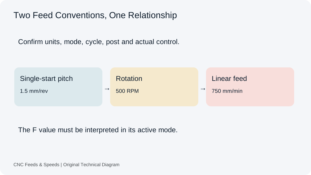
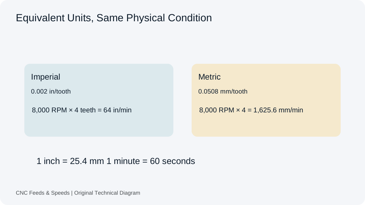
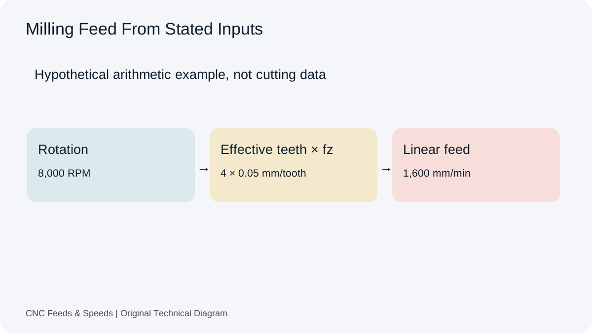
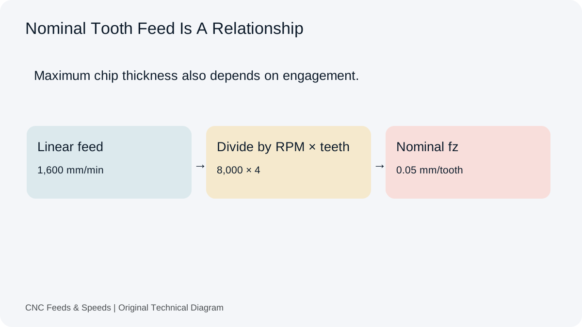
At a source feed of 0.15 mm/rev, 500 RPM corresponds to 75 mm/min. That multiplication preserves feed per revolution, but it does not make the higher cutting speed acceptable for the drill and material. A feed calculation cannot repair a tool-speed mismatch. Use the drilling workspace to inspect these quantities separately rather than hide the incompatibility behind one final feed.
Tool Construction Changes The Source Data
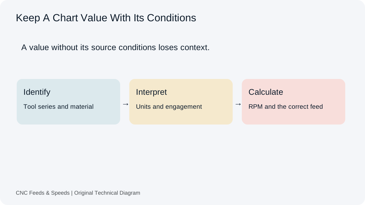
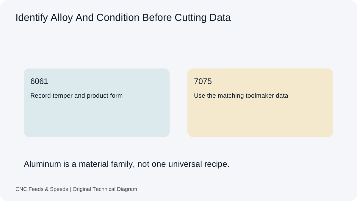
HSS, cobalt-alloy HSS, solid carbide and indexable drills do not share one cutting-speed recommendation. Diameter, point geometry, coating, hole depth, material condition and coolant delivery also matter. A material row from an end-mill chart is not a drilling specification. Identify the exact drill series and obtain guidance for the actual application before comparing the requested condition with the machine range.
The tool-material guide explains why shared arithmetic does not mean interchangeable source data. A change from one drill construction to another may solve one limitation while introducing another, such as rigidity, runout or coolant requirements. Do not select a tool solely because its advertised speed range seems to match a fast spindle.
The Hole May Need Another Process
When the machine and drill cannot support the same condition, the answer may be a different tool, a different machine or a different method of making the feature. Those alternatives require their own checks. Circular interpolation, for example, needs suitable cutter geometry, enough room for the centre path, adequate support and a correct feed interpretation. It is not automatically possible just because the hole is larger than an available end mill.
Separate feature requirements from the first tool proposed. Consider the required diameter, depth, tolerance, finish, access, quantity and exit condition. A pilot hole, bored feature or operation on another machine may be appropriate in some cases, but there is no universal substitute. The calculation stage should reveal the mismatch clearly enough for the process decision to be made.
Why The Basic RPM Ceiling Field Is Not Enough
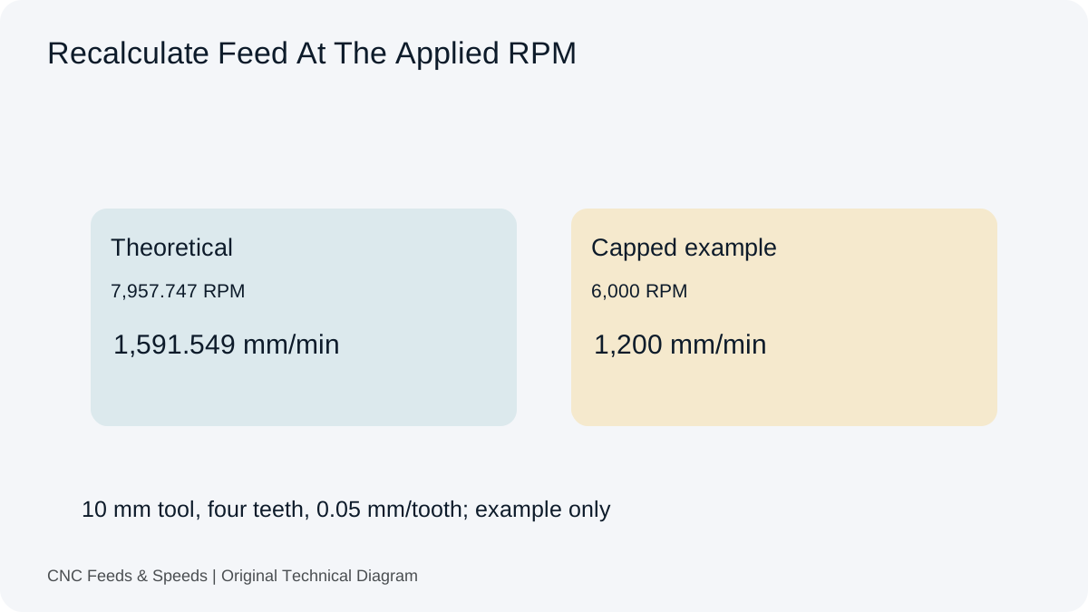
The advanced calculators on this site can apply an upper spindle ceiling and recalculate dependent results. They do not model the lower torque curve, a minimum cooling requirement or the spindle’s full power envelope. Entering a low maximum RPM does not create a minimum-speed model. Review the spindle-limit explanation when interpreting what a capped result does and does not establish.
A machine profile would need verified specifications, units, revision and a clear source before it could provide useful constraints. A brand name or machine category alone is insufficient. Two machines described as desktop routers may use different spindles, drives, controllers and workholding. Applying a generic router correction factor would conceal those differences instead of addressing them.
Look Beyond RPM When The Drill Complains
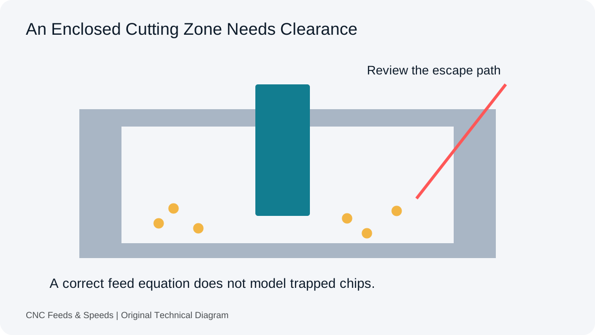
Poor chip evacuation, excessive unsupported length, runout, unsuitable point geometry, a damaged edge or weak workholding can all complicate a drilling operation. A noise change does not identify one cause on its own. Preserve the source inputs and inspect the setup through the machine’s normal procedures. Stop and investigate abnormal cutting rather than repeatedly increase or reduce feed in search of a quieter number.
For a known actual RPM and verified source feed per revolution, the feed-per-revolution calculator can audit an existing linear command. It does not determine the feed that the drill ought to use. Keep a record of the drill part number, material grade, actual depth, coolant method and any cycle settings so the arithmetic can be separated from the physical problem.
Use Technical References For The Relationship
Sandvik Coromant’s drilling formulas define the relationship between diameter, cutting speed, rotation and feed. They support the calculations in this article. They do not provide a universal speed prescription for an unidentified drill, and they do not replace the documented operating range of a specific spindle.
Before another attempt, establish which condition is being changed and why. Save the calculated cutting speed at the actual RPM, not only the original requested value. Keep any proposed condition distinct from a measured outcome. The setup-record guide explains how to preserve that distinction so a future operator does not mistake an unresolved experiment for a validated drilling recipe.
Questions About Fast Spindles And Drilling
Can I Keep Chip Load Constant By Raising Feed?
The feed-per-revolution relationship can be preserved mathematically, but that does not make an excessive cutting speed or unsuitable tool acceptable.
Does The Site Model Minimum Spindle Torque?
No. The upper-limit fields do not represent a lower torque or cooling envelope. Use the actual machine and spindle documentation.
Should Every Router Hole Be Interpolated Instead?
No. The feature, tooling, machine and operation determine whether interpolation is suitable. It is a separate process decision, not a universal replacement for drilling.
Help Improve This Resource
Request A Tool
Describe the calculation your workflow needs, the inputs you already have and the output you want to check. Include units and an example without confidential job details.
Request A ToolReport An Error
Share this page address, the entered values and the result you expected. Include the source of your comparison so the formula, units and explanation can be investigated.
Report An ErrorCNC Feeds & Speeds Editorial Desk
The site brings calculation tools and machining references into one workspace. Use the editorial and site information to understand its purpose and limitations. Send corrections with a reproducible example through the error report form.