A drill tip can reach the far face before the full hole diameter has passed through it. That difference matters when a drawing specifies cylindrical depth or a CAM operation adds tip-through allowance. Establish the depth definition and the tool geometry before turning the dimension into a Z command.
Tip Depth And Cylindrical Depth Differ
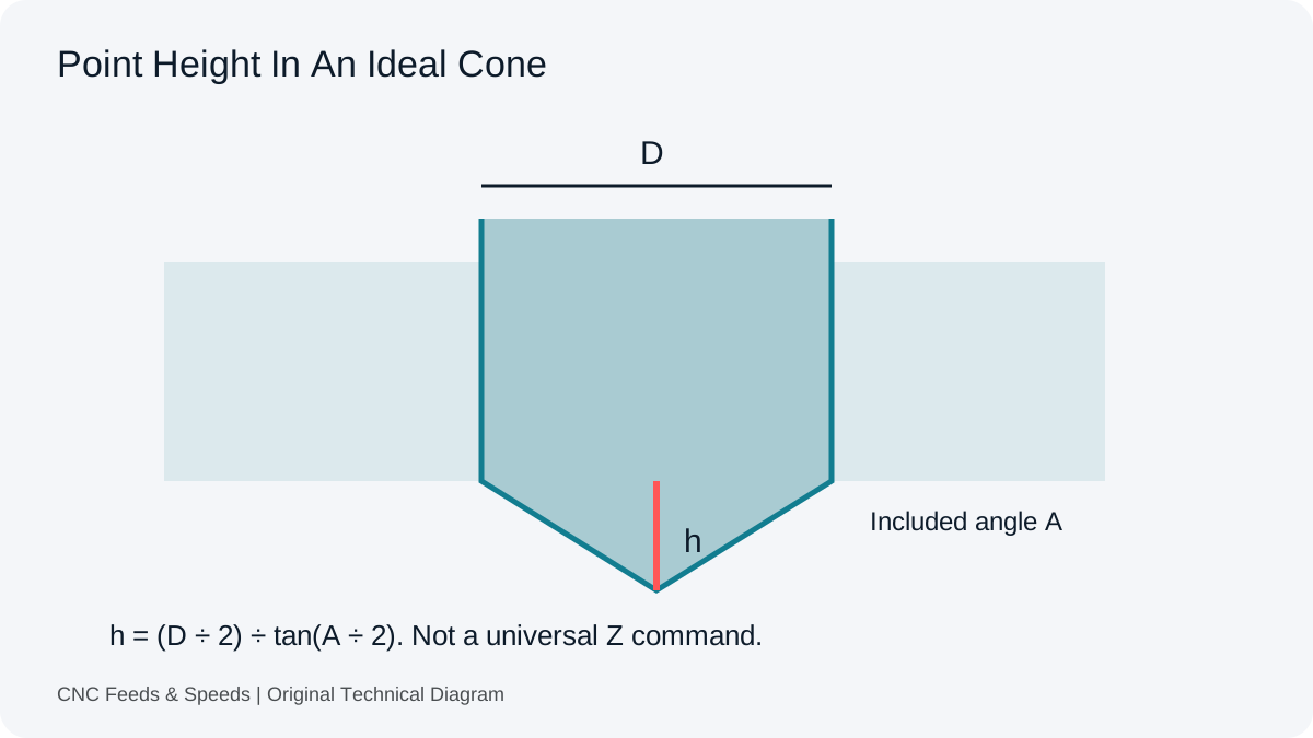
A pointed drill creates a conical region ahead of the full-diameter cylindrical hole. In a blind hole, the tip may reach a specified depth while the cylindrical portion remains shallower. In a through hole, full-diameter breakthrough generally requires the tip to travel beyond a flat exit face. The drawing and manufacturing plan must establish which depth is intended.
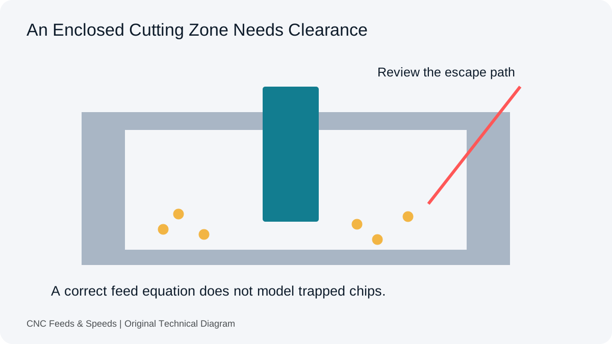
Our drilling reference separates geometry and setup from feed arithmetic. A calculator that converts RPM and feed per revolution does not establish the permitted end position. The datum, tool length reference, workpiece thickness and clear space beyond the part all affect how a geometric allowance relates to the machine program.
An Independent Ideal-Cone Derivation
For an ideal centred conical point of diameter D and included angle A, the right triangle gives tan(A/2) = (D/2) ÷ h. Rearranging gives point height h = (D/2) ÷ tan(A/2). This is an independent geometric derivation, not a claim that every drill point is a perfect cone or that a particular manufacturer’s drawing uses this exact definition.
For a 10 mm diameter and a 118 degree included angle, ideal point height is about 3.004 mm. At 135 degrees, the same ideal model gives about 2.071 mm. Use consistent angle units in any calculation. Diameter must be positive, and the included angle must be between zero and 180 degrees. An actual split point, web or specialised geometry needs the manufacturer’s dimensions.
Do Not Convert The Example Into A Universal Depth
For a hypothetical 12 mm flat plate, the thickness plus the ideal 118 degree point height gives about 15.004 mm of tip penetration from the entry face before any additional chosen clearance. That is a geometric illustration. It is not a universal Z value. An angled exit, a step, a nearby clamp or a different tool reference can invalidate a simple thickness-plus-point interpretation.
Autodesk’s drill-operation reference documents depth-related controls (including drill-tip treatment). Use the actual operation definition and post output. Do not add a manual point allowance on top of an equivalent automatic allowance without checking whether the same geometry has already been included.
Breakthrough Feed Is A Separate Decision
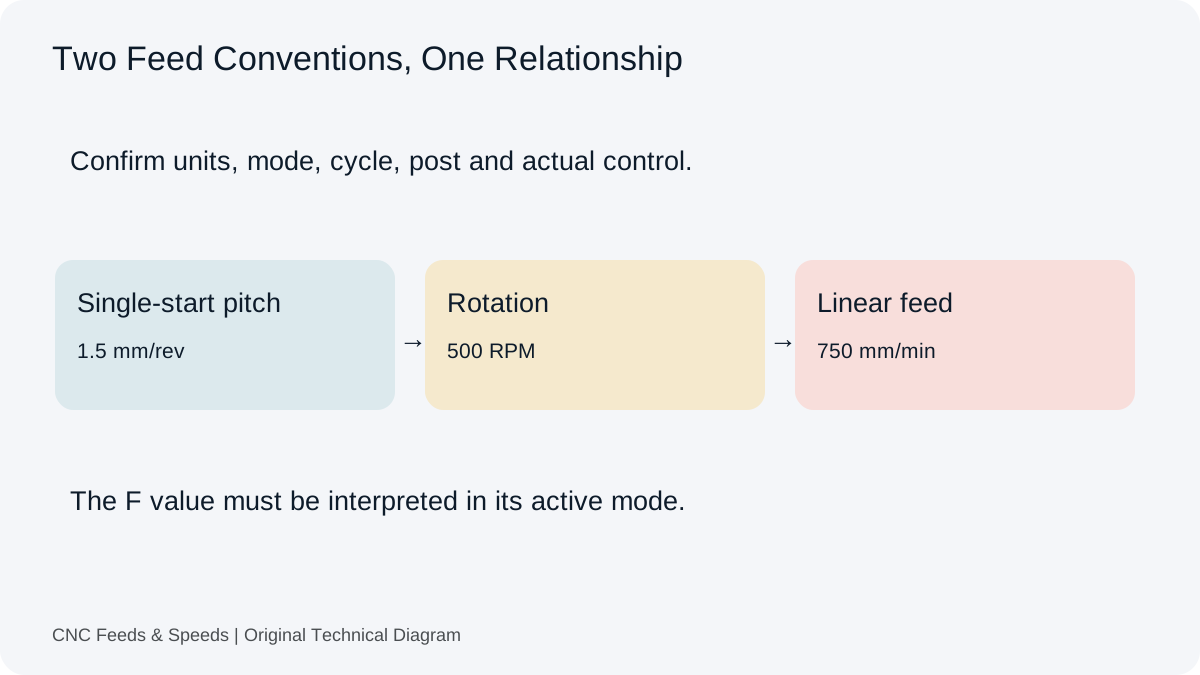
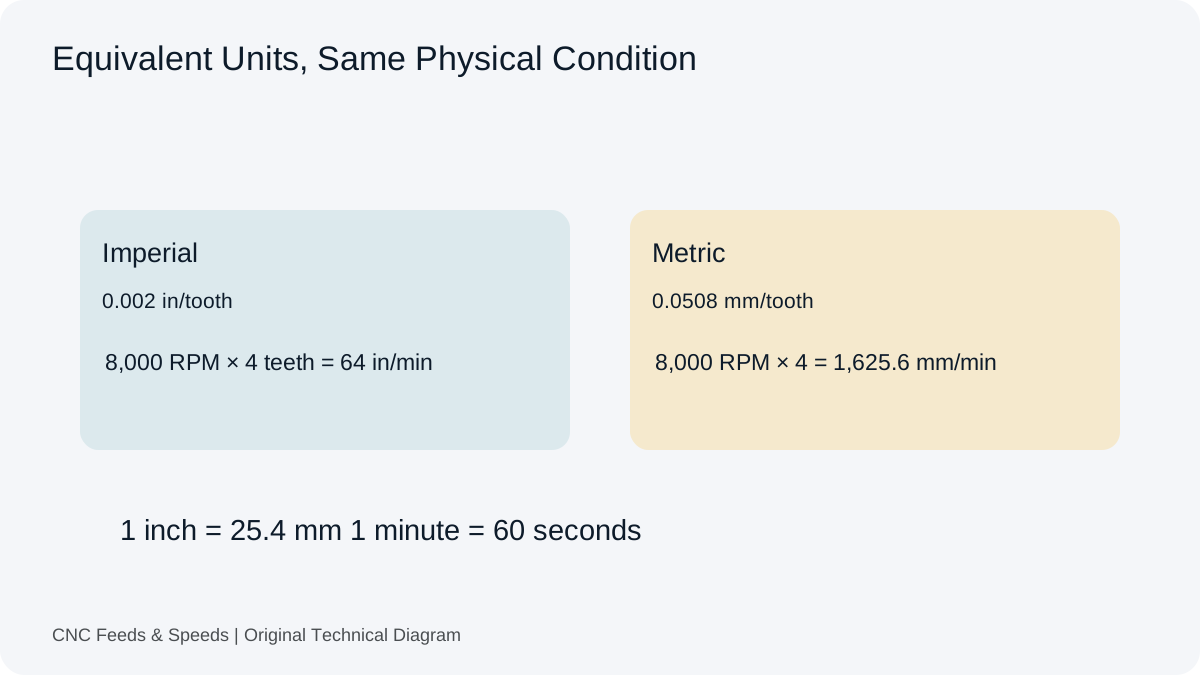
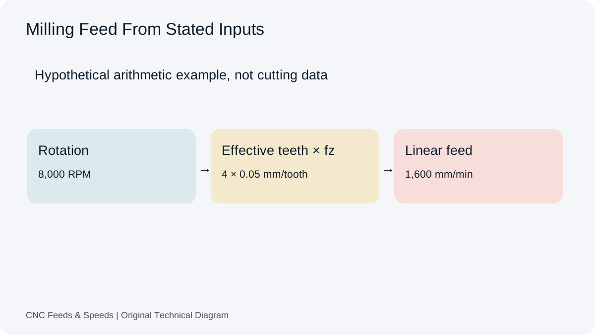
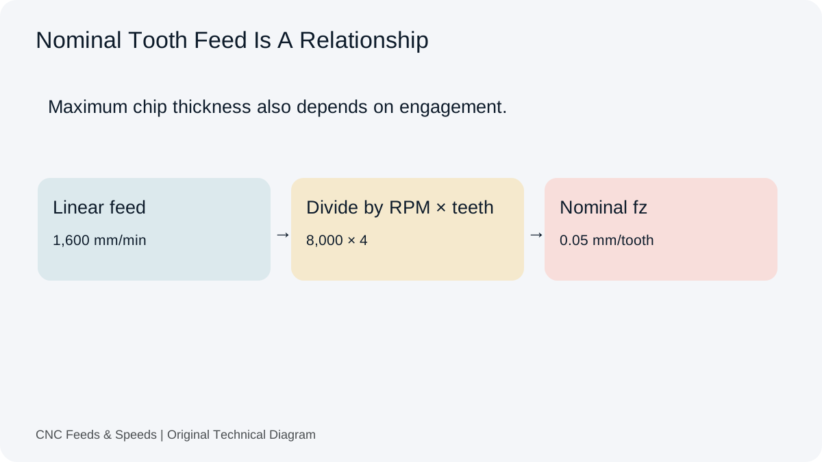
A geometric point allowance describes travel. A breakthrough feed reduction, where specified for an application, describes cutting behaviour near the exit. They are different decisions. Our feed-per-revolution check can audit a stated feed, but it does not choose an exit strategy or predict burr formation.
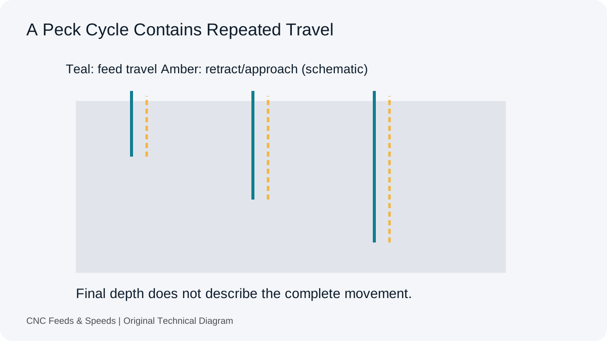
Likewise, extra tip travel changes a time estimate only to the extent that it adds movements within the stated model. The peck-cycle guide explains why depth divided by feed may still omit retracts and approaches. Keep travel geometry, feed convention and cycle sequence in separate fields rather than hide them in one allowance.
Why The Question Comes Up In CAM
An Autodesk drill-tip discussion from January 2018 begins with a request for automatic compensation. Replies explain that the relevant tip-through and angle treatment already existed, and the author acknowledges the clarification. The complete exchange illustrates uncertainty about a control, not evidence that the software lacks the feature. It is discussion context, not the authority for the ideal-cone equation.
For the job record, preserve the drill specification, point definition, datum, required cylindrical depth, chosen clearance and operation settings. Use the setup-record guide to keep derived geometry separate from measured tool and part information. A clear record avoids repeating an allowance simply because a previous program contained an unexplained extra depth.
Depth Questions
Does Reaching The Exit Face Complete The Full-Diameter Hole?
Not necessarily. A pointed tool may need additional travel for its full diameter to pass the face, subject to actual geometry and clearance.
Is The Cone Formula An Exact Model Of Every Drill?
No. It is an ideal geometric model. Use the actual tool drawing and operation requirements where they differ.
Should I Always Add The Calculated Height In CAM?
No. First determine what the operation already includes and whether the drawing, datum and fixture permit that travel.
Help Improve This Resource
Request A Tool
Describe the calculation your workflow needs, the inputs you already have and the output you want to check. Include units and an example without confidential job details.
Request A ToolReport An Error
Share this page address, the entered values and the result you expected. Include the source of your comparison so the formula, units and explanation can be investigated.
Report An ErrorCNC Feeds & Speeds Editorial Desk
The site brings calculation tools and machining references into one workspace. Use the editorial and site information to understand its purpose and limitations. Send corrections with a reproducible example through the error report form.