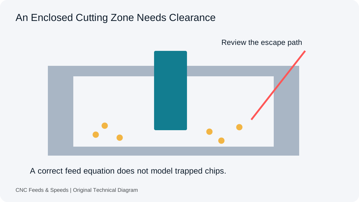
A pocket can trap chips even when RPM and feed are calculated consistently. Chips that cannot leave the cutting zone may be recut, interfere with the edge or contribute to material buildup. Before changing feed again, identify the operation, the tool’s available chip space and the route by which chips are expected to leave.
Name The Operation Accurately
A drilled hole, an interpolated bore and a pocket made with an end mill use different tool contact and chip-clearance conditions. A complaint described only as a hole problem is difficult to diagnose. The drilling workspace follows drill feed conventions, while milling uses effective teeth and tooth feed. Establish which process is actually being used before comparing results.
In a Carbide 3D discussion about small circular pockets, the user describes material adhering to a tool and difficulty clearing chips. This provides the practical problem behind the article. Its reported settings and suggested remedies are not reproduced as general cutting instructions.
Inspect The Tool And Contact
Tool diameter, flute design, reach, edge condition and the enclosed space affect what happens to chips. An entry into solid material may be particularly demanding. The Harvey Performance entry-method guide discusses the relationship between entry and chip clearance. Use it as technical context, then obtain guidance for the actual tool and feature.
A tool coated with work material does not establish one cause by itself. Source cutting conditions, material adhesion, edge condition and evacuation can interact. Stop and inspect abnormal cutting through the machine’s established procedures. Do not approach moving tooling to clear chips or change coolant arrangements based on an online description.
Entry Can Change The Problem
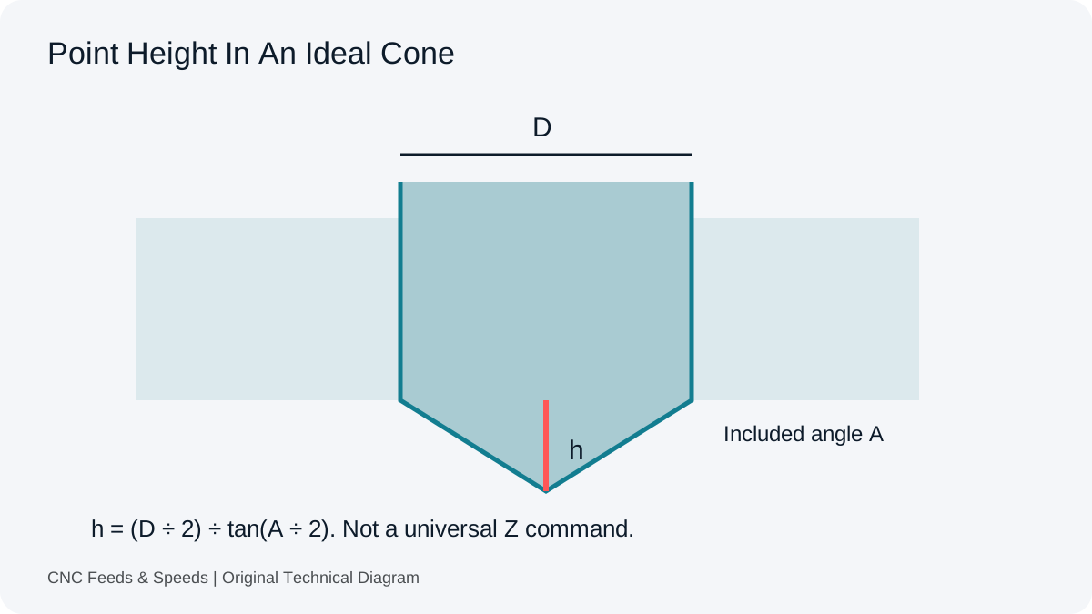
A straight axial entry and a ramp expose the cutter to different contact. The entry-feed guide explains why one cannot be treated as a fixed percentage of the other without tooling support. A centre-cutting designation also does not guarantee that every enclosed plunge depth is suitable.
If a different entry is considered, verify its geometry, clearance and toolmaker limits. An interpolated feature needs a defined centre path, and a helix adds axial motion. Changing the method without reviewing those details may move the problem rather than resolve it. Keep the proposed process distinct from a condition already observed on the machine.
Material And Coolant Context Matter
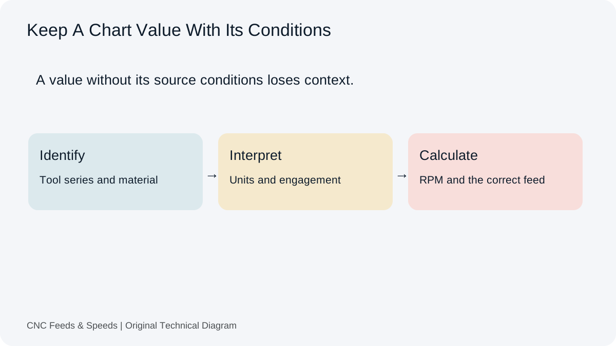
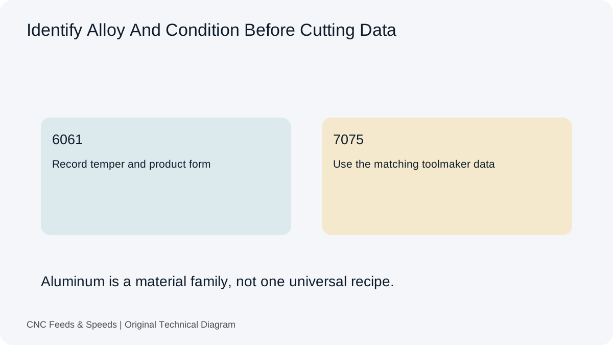
Alloy, condition, coating and edge geometry can affect adhesion and chip formation. The aluminum reference explains why a material family name is not enough to select cutting data. Keep the exact tool specification and the source’s coolant or lubrication assumptions with the record. A source that assumes one delivery method does not establish another method’s capability.
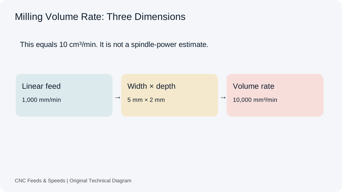
Air, fluid and through-tool delivery have application-specific requirements. This article does not prescribe a universal pressure, nozzle position or peck depth. Machine enclosure, tool guidance and the actual process determine what is appropriate. An evacuation change should follow those instructions and be assessed as a process change, not a numerical correction inside the feed formula.
Check The Arithmetic Without Expecting It To Explain Everything
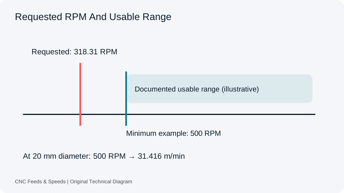
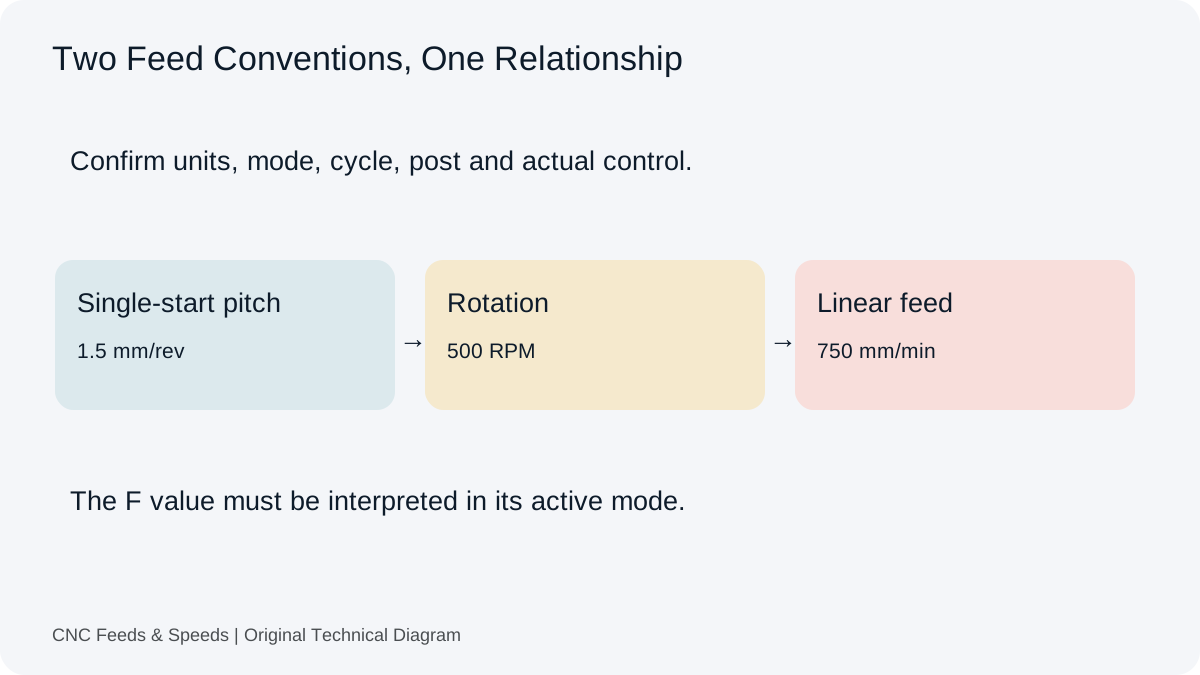
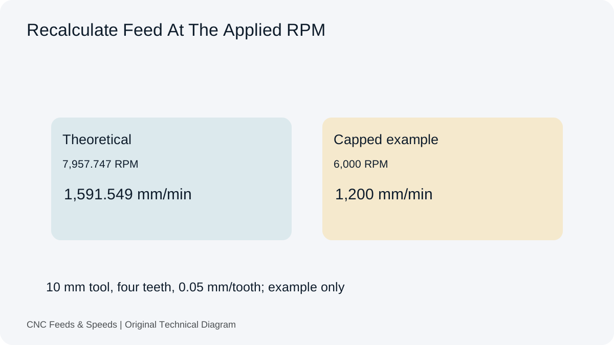
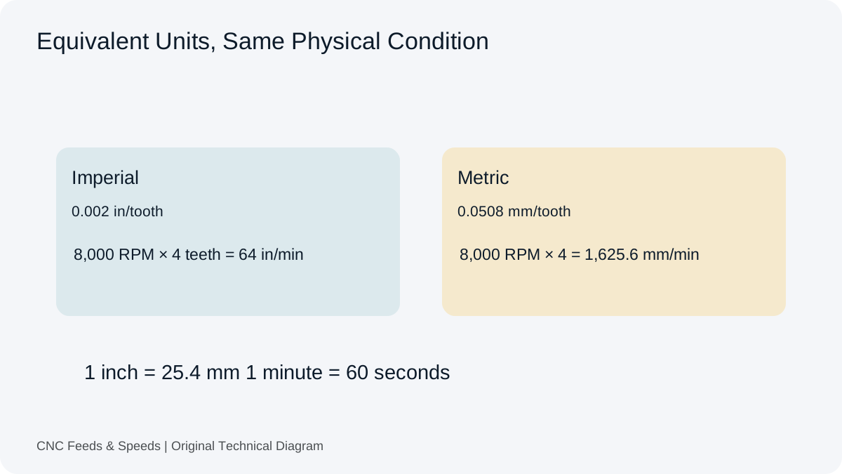
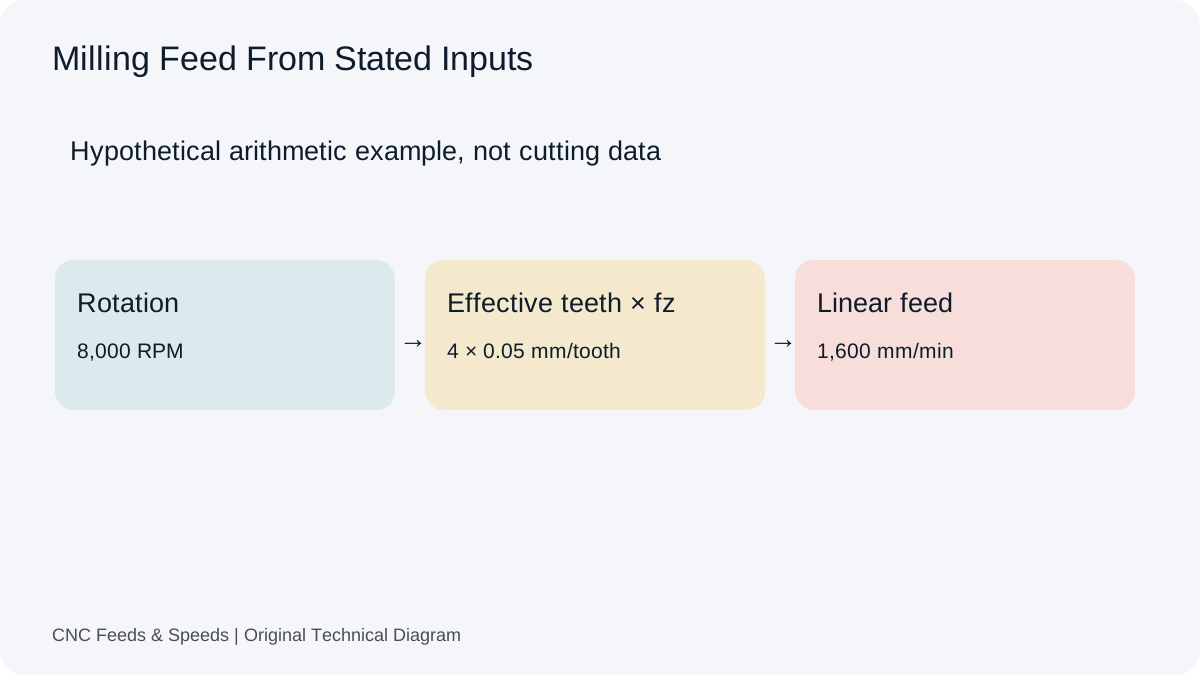
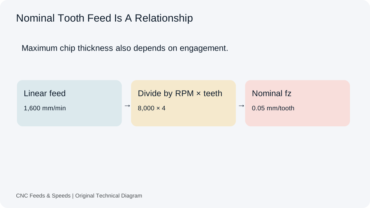
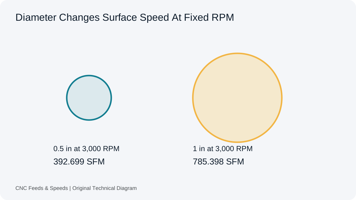
Use the chip-load calculator to verify nominal tooth feed from actual RPM, effective teeth and linear feed. A consistent result rules out some arithmetic mistakes, but not an obstructed cutting zone or damaged edge. Keep the input audit separate from the physical diagnosis.
Record engagement, entry, depth, tool reach, coolant method and observed chips. The setup-record workflow helps preserve what changed between attempts. If several parameters and the evacuation method change together, describe the result honestly rather than attribute improvement to one unisolated cause.
Chip-Clearance Questions
Does Correct Chip Load Guarantee Good Evacuation?
No. The equation does not model chip space, depth, coolant access, tool condition or the route out of an enclosed feature.
Should Every Deep Feature Use Pecking?
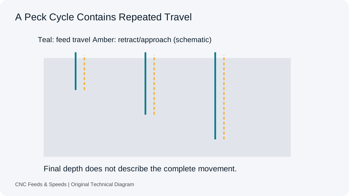
No. Tool construction and supplier instructions determine the applicable method. Drilling and milling require different process decisions.
Can A Forum Feed Be Reused For My Pocket?
Not without matching the actual tool, material, geometry and machine conditions. Treat the discussion as context, not validated cutting data.
Help Improve This Resource
Request A Tool
Describe the calculation your workflow needs, the inputs you already have and the output you want to check. Include units and an example without confidential job details.
Request A ToolReport An Error
Share this page address, the entered values and the result you expected. Include the source of your comparison so the formula, units and explanation can be investigated.
Report An ErrorCNC Feeds & Speeds Editorial Desk
The site brings calculation tools and machining references into one workspace. Use the editorial and site information to understand its purpose and limitations. Send corrections with a reproducible example through the error report form.