Check synchronized tapping feed from pitch or TPI, then review spindle limits and thread assumptions.
Tapping Feed From RPM And Pitch
Use the basic panel when spindle RPM and thread pitch are already known. The advanced panel calculates RPM from source cutting speed and tap diameter before calculating synchronized feed. Both panels use a single-start thread relationship, so confirm the thread specification first.
Used For
Check metric tap feed or imperial TPI feed before reviewing the machine tapping cycle.
Enter the values you know. The result is calculated in your browser.
Calculation only. Verify toolmaker data, material grade, engagement, machine limits, workholding and actual cutting conditions before production.
Tapping Speed And Synchronized Feed
Use the fuller calculation when additional process and machine variables matter.
Tapping Feed Advanced
Enter the values you know. The result is calculated in your browser.
Calculation only. Verify toolmaker data, material grade, engagement, machine limits, workholding and actual cutting conditions before production.
Tapping Quick Checks
The main tapping panels already calculate synchronized feed. These supporting checks answer different questions: surface speed at an existing RPM and time for one defined feed stroke. Neither check simulates the complete tapping cycle.
Check Surface Speed At Tap RPM
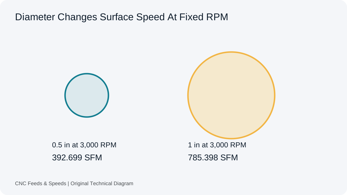
Inspect the surface speed implied by tap diameter and an existing spindle setting. Compare it with the applicable tool reference. Thread pitch determines synchronized feed separately and is not an input to this surface-speed check.
Open Tap Surface Speed
Metric speed = π × diameter × RPM ÷ 1000. Example: 10 mm at 500 RPM gives about 15.71 m/min.
Tap Surface Speed Check
Enter the values you know. The result is calculated in your browser.
Calculation only. Verify toolmaker data, material grade, engagement, machine limits, workholding and actual cutting conditions before production.
Estimate the time for a stated feed travel at the synchronized linear feed. Establish travel from the actual cycle requirements. Reversal, spindle acceleration, dwell, approach and withdrawal time are not included automatically.
Open Feed Stroke Time
One-stroke time = travel ÷ synchronized feed. Example: 15 mm ÷ 750 mm/min = 0.02 minute (1.2 seconds). This is not total cycle time.
Single Tapping Feed Stroke Time
Enter the values you know. The result is calculated in your browser.
Calculation only. Verify toolmaker data, material grade, engagement, machine limits, workholding and actual cutting conditions before production.
Calculate advance per revolution from pitch or TPI and the number of thread starts. Use this as a separate geometry check for a specified thread. It does not make the main single-start tapping panels or a machine cycle suitable for a multi-start application.
Open Thread Lead Check
Metric lead = pitch × starts. Imperial lead = starts ÷ TPI. Examples: 1.5 mm pitch with 3 starts gives 4.5 mm/rev; 20 TPI with 2 starts gives 0.1 in/rev.
Thread Lead From Pitch And Starts
Enter the values you know. The result is calculated in your browser.
Calculation only. Verify toolmaker data, material grade, engagement, machine limits, workholding and actual cutting conditions before production.
Enter a whole number of starts of at least one. Confirm the full thread specification and control requirements separately. Primary threading definitions.
Tap Speed And Feed Follow Thread Geometry
For a conventional single-start thread, one spindle revolution advances the tap by one pitch. That relationship determines feed once RPM is known. The source cutting speed still comes from the tap supplier for the tool, material and application. Flute count does not multiply the feed as it does in the milling equation.
Check The Thread Before Entering Values
Read the thread designation and establish whether the source states metric pitch or threads per inch.
In the basic panel, enter actual RPM and the pitch or TPI required by the selected unit mode.
In the advanced panel, enter supplier cutting speed, tap diameter, thread value and the spindle ceiling you intend to apply.
Compare the synchronized feed with the expected machine feed mode. This page does not generate a tapping cycle or confirm control compatibility.
Metric Pitch And Imperial TPI Examples
A single-start 1.5 mm pitch at 500 RPM requires 500 × 1.5 = 750 mm/min. At the same RPM, a 20 TPI thread advances 1 ÷ 20 = 0.05 inch per revolution and requires 25 in/min. A TPI value is a thread count per inch; it must not be read as an inch pitch.
For the advanced calculation, an illustrative 15 m/min at 10 mm diameter gives 477.46 RPM. A 1.5 mm pitch then gives about 716.20 mm/min. If a 400 RPM ceiling applies, this panel uses 400 RPM and produces 600 mm/min. These inputs illustrate synchronization arithmetic, not a tap speed recommendation.
Pitch, Lead And Multiple Starts
Pitch is the distance between adjacent threads. Lead is the advance during a full revolution. They are equal for a single-start thread; multiple starts make the lead larger than the pitch. The main tapping panels use the single-start relationship. The separate Thread Lead quick tool checks pitch and starts, but does not validate a multi-start machine cycle. Resolve the geometry and machine requirements before applying a feed.
The Hole And The Machine Cycle Remain Separate
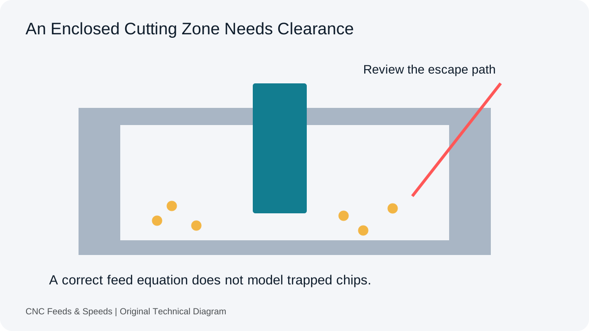
This calculation does not select a tap drill, percentage of thread, tap style or compensation holder. Hole preparation, available depth and chip control need the relevant tooling instructions. The tapping reference separates those preparation questions from the formula. Use the machine manual for synchronized spindle motion, reversal and the active feed mode.
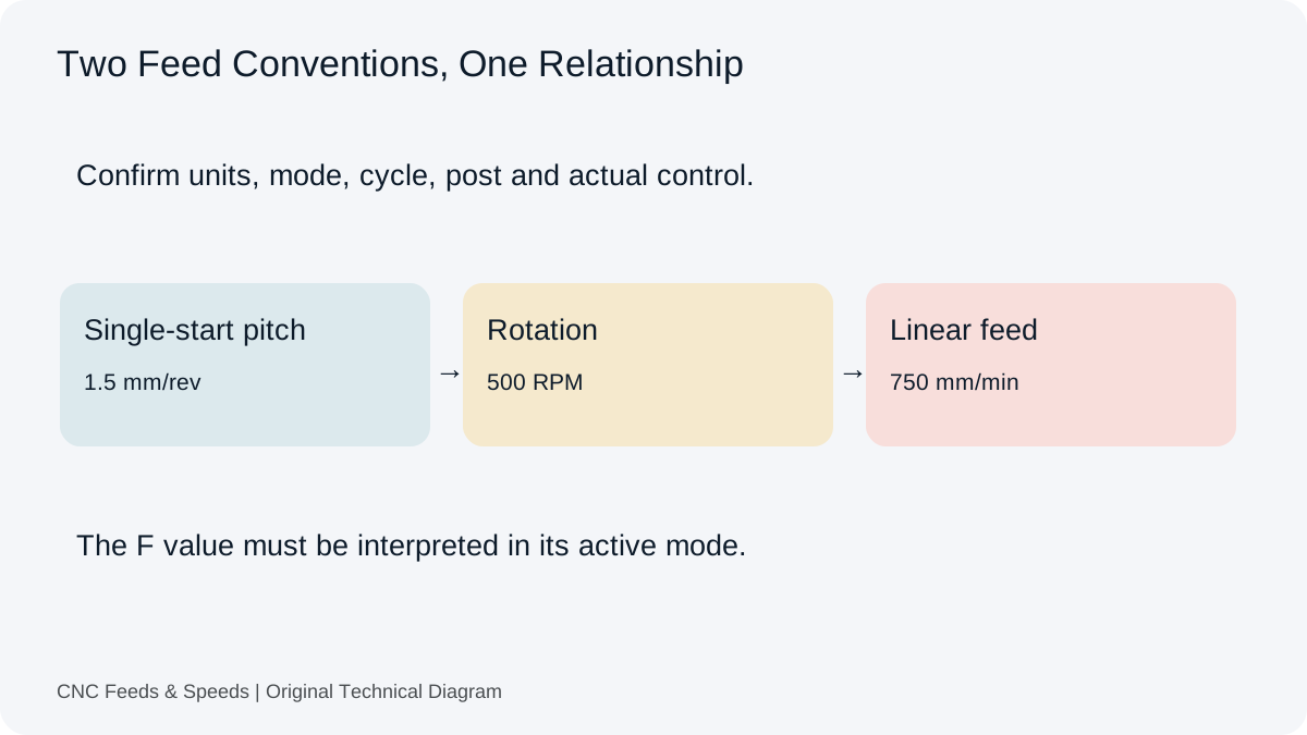
A single-start 1.5 mm pitch at 500 RPM corresponds to 1.5 mm per revolution or 750 mm per minute. Those values express the same relationship in different feed modes. The posted program must match the units and mode expected by the particular machine, control and tapping cycle.
The Haas mill G84 reference is one controller-specific example, not a universal tapping program. Compare the active units, cycle, feed mode, spindle command and post-processor documentation before interpreting an F value. This page does not generate machine-ready G-code or choose holder compensation.
Pitch And Lead Must Stay Distinct
Lead equals pitch multiplied by the number of starts. The thread-lead quick tool below checks that geometry, but it does not change the main tapping calculator into a multi-start synchronisation tool. Keep the single-start tapping-feed calculation within its stated purpose and verify the actual thread and control requirements separately.
Choose The Hole Reference Before Tapping
Synchronized feed checks the relationship between rotation and thread lead. It does not choose the prepared-hole diameter. Identify the thread designation, tap construction and work material before opening a drill chart, then retain the supplier’s hole limits with the tapping setup rather than copying a size from an unrelated tap.
Thread Or Tap Type
What To Establish
Reference Route
Metric ISO cut tap
Nominal diameter, pitch, required tolerance and the exact cutting tap. Keep blind-hole and through-hole details visible.
Use the tap supplier’s drill/minor-diameter limits for the selected product and material.
UNC, UNF Or UNEF cut tap
Full designation, TPI, thread class and tap identifier. A shared nominal diameter does not establish the same pitch or hole.
Exact thread standard, size, taper, required engagement and supplier preparation instructions. Preserve any required reaming step.
Use the applicable thread specification and pipe-tap documentation. A straight metric or UN drill rule does not define this preparation.
Record A Hole Range, Not An Unqualified Number
A useful setup record identifies the nominal thread, supplier tap code, stated drill or minor-diameter range, material condition and reference revision. Record the actual prepared hole separately from the nominal drill label. A drill chart is a starting reference; the thread and part still need the inspection required by the drawing.
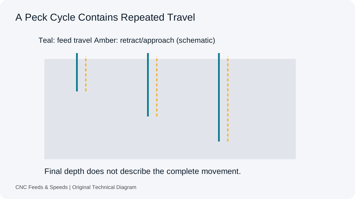
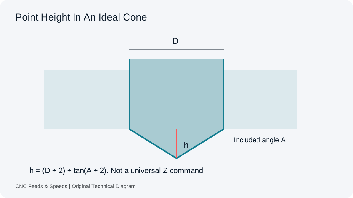
Use the posted tapping-feed guide to check how the control interprets feed, and the drill-point tool when tip travel differs from full-diameter depth. The reaming workspace addresses a separate prepared-hole operation if the documented process calls for it.
Tapping Questions
Should I Enter Tap Flute Count?
No. Synchronized tapping feed follows thread lead per revolution. A milling feed per tooth multiplied by flute count describes a different operation.
Why Does Reducing RPM Change Tapping Feed?
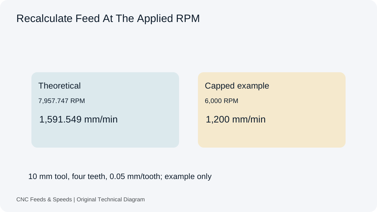
For the same single-start pitch, feed per minute changes in direct proportion to RPM. The advanced panel recalculates feed after its spindle ceiling is applied. The machine must still synchronize the motions through its supported cycle.
Is This A Tap Drill Calculator?
No. It calculates rotation and feed relationships. Request a separate hole-sizing tool through Request A Tool if that is the calculation you need; do not treat the tap diameter input as a recommended drill size.
Help Improve This Resource
Request A Tool
Describe the calculation your workflow needs, the inputs you already have and the output you want to check. Include units and an example without confidential job details.
Share this page address, the entered values and the result you expected. Include the source of your comparison so the formula, units and explanation can be investigated.
The site brings calculation tools and machining references into one workspace. Use the editorial and site information to understand its purpose and limitations. Send corrections with a reproducible example through the error report form.
Related Articles
Continue with the calculation, setup or troubleshooting question closest to your task.
When A Router Cannot Run Slowly Enough To Drill
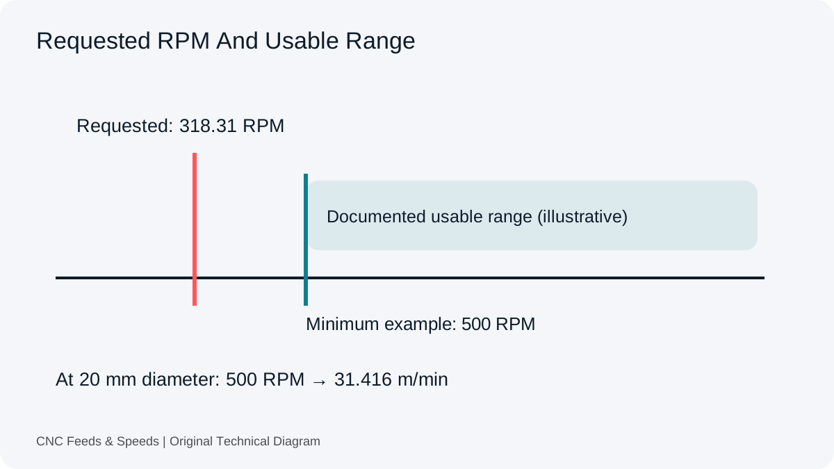
Compare drill requirements with the usable spindle range. Calculate achieved cutting speed without treating feed adjustment as a cure for incompatible tooling.