Calculate drill RPM, work from feed per revolution and check carbide-drill source data.
Drill RPM From Cutting Speed
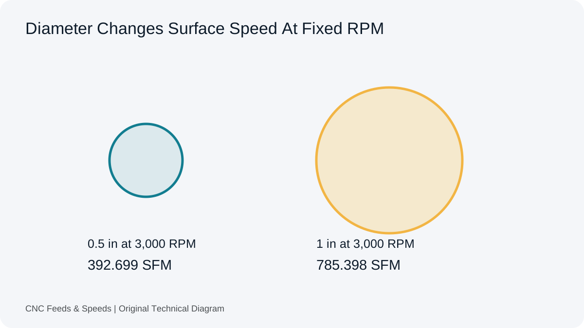
Calculate rotational speed from drill diameter and the supplier cutting speed. Then compare an entered linear feed with actual RPM in the second panel. The two panels answer different questions: the first finds RPM, while the second checks feed per revolution.
Used For
Audit drill speed and feed inputs for a specified holemaking operation.
Formula
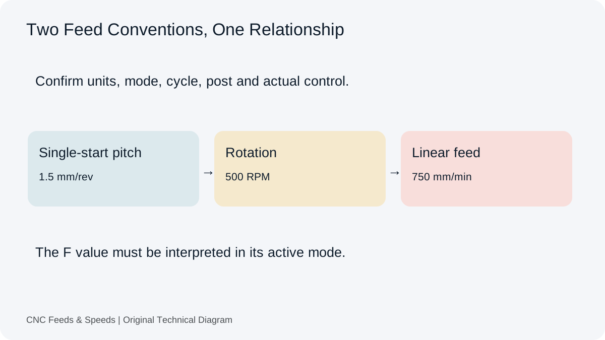
RPM = 1000 × Vc ÷ (π × D). Linear feed = actual RPM × feed per revolution.
Spindle Speed Basic
Enter the values you know. The result is calculated in your browser.
Calculation only. Verify toolmaker data, material grade, engagement, machine limits, workholding and actual cutting conditions before production.
Drill Feed Per Revolution Check
Use the fuller calculation when additional process and machine variables matter.
Feed Per Rev Advanced
Enter the values you know. The result is calculated in your browser.
Calculation only. Verify toolmaker data, material grade, engagement, machine limits, workholding and actual cutting conditions before production.
Drilling Quick Tools
Once actual drill RPM is established, calculate linear feed from the supplier feed per revolution. Use that linear feed for a constant-travel time estimate. The tools do not choose hole depth strategy, coolant delivery or a peck cycle.
Calculate Drill Linear Feed
Multiply actual RPM by source feed per revolution to obtain feed per minute. There is no milling flute-count multiplier. Use the spindle setting that will run after any speed limit has been applied.
Estimate time for a defined feed distance at the calculated linear feed. Establish the required tool travel separately from nominal hole depth. Peck retractions, breakthrough allowance, dwell and rapid moves need their own accounting.
Open Hole Travel Time
Time = feed travel ÷ linear feed. Example: 30 mm ÷ 300 mm/min = 0.1 minute (6 seconds), excluding other cycle events.
Drill Feed Travel Time
Enter the values you know. The result is calculated in your browser.
Calculation only. Verify toolmaker data, material grade, engagement, machine limits, workholding and actual cutting conditions before production.
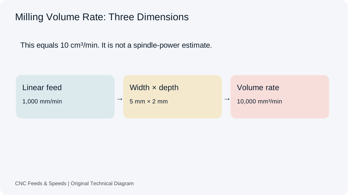
Estimate volume removed by a full circular drill section at a known linear feed. Use the solid drill diameter and feed per minute. The model does not subtract a pre-existing hole or describe annular drilling, countersinking or changing engagement.
Open Solid Drilling MRR
MRR = (π × diameter² ÷ 4) × linear feed. Example: 10 mm at 300 mm/min gives 23,561.94 mm³/min (23.56 cm³/min).
Solid Circular Drilling Removal Rate
Enter the values you know. The result is calculated in your browser.
Calculation only. Verify toolmaker data, material grade, engagement, machine limits, workholding and actual cutting conditions before production.
This is the circular-area form of the steady drilling volume relationship. Sandvik Coromant drilling definitions also express it using cutting speed and feed per revolution.
Drilling Speed And Feed Use Two Relationships
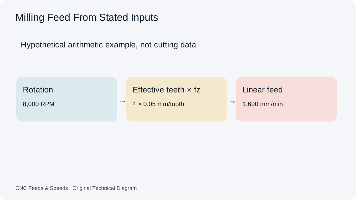
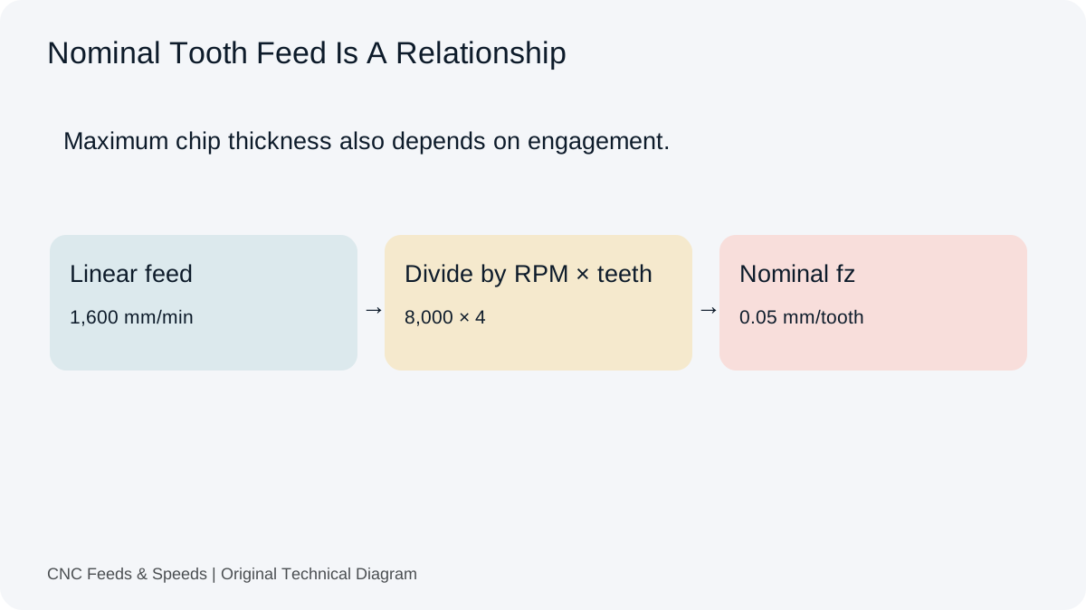
A drill speed calculation converts surface speed and drill cutting diameter into RPM. Drilling feed rate usually follows actual RPM multiplied by source feed per revolution. Keep that convention visible when reading a chart: a value in mm/rev is not a milling tooth feed and should not be multiplied again by the drill flute count.
Use The RPM Panel Before The Feed Check
Select the source units and enter drill cutting diameter with supplier cutting speed in the basic panel.
Calculate RPM and establish the actual spindle setting after any machine limit.
Multiply actual RPM by source feed per revolution to obtain linear feed. Use the Drill Linear Feed quick tool below for that multiplication; the second main panel does the reverse check.
Enter linear feed and actual RPM in the second panel. Its extra speed and diameter fields provide a comparison, not a replacement for the entered RPM.
A Drill Feed Rate Example
For illustrative inputs of 80 m/min and 10 mm diameter, RPM = 1000 × 80 ÷ (π × 10) = 2,546.48. A separately selected source feed of 0.15 mm/rev gives 2,546.48 × 0.15 = 381.97 mm/min. Entering 381.97 mm/min and 2,546.48 RPM in the second panel returns approximately 0.15 mm/rev. The values demonstrate arithmetic, not a drilling recommendation.
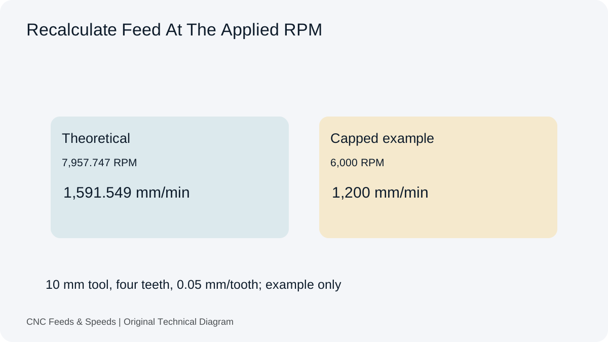
If the actual setting is 2,000 RPM, the same 0.15 mm/rev gives 300 mm/min. Retaining 381.97 mm/min instead would raise feed per revolution to about 0.191 mm/rev. This is why a spindle change requires another feed check rather than only a new RPM entry.
Carbide Drill Data And Hole Conditions
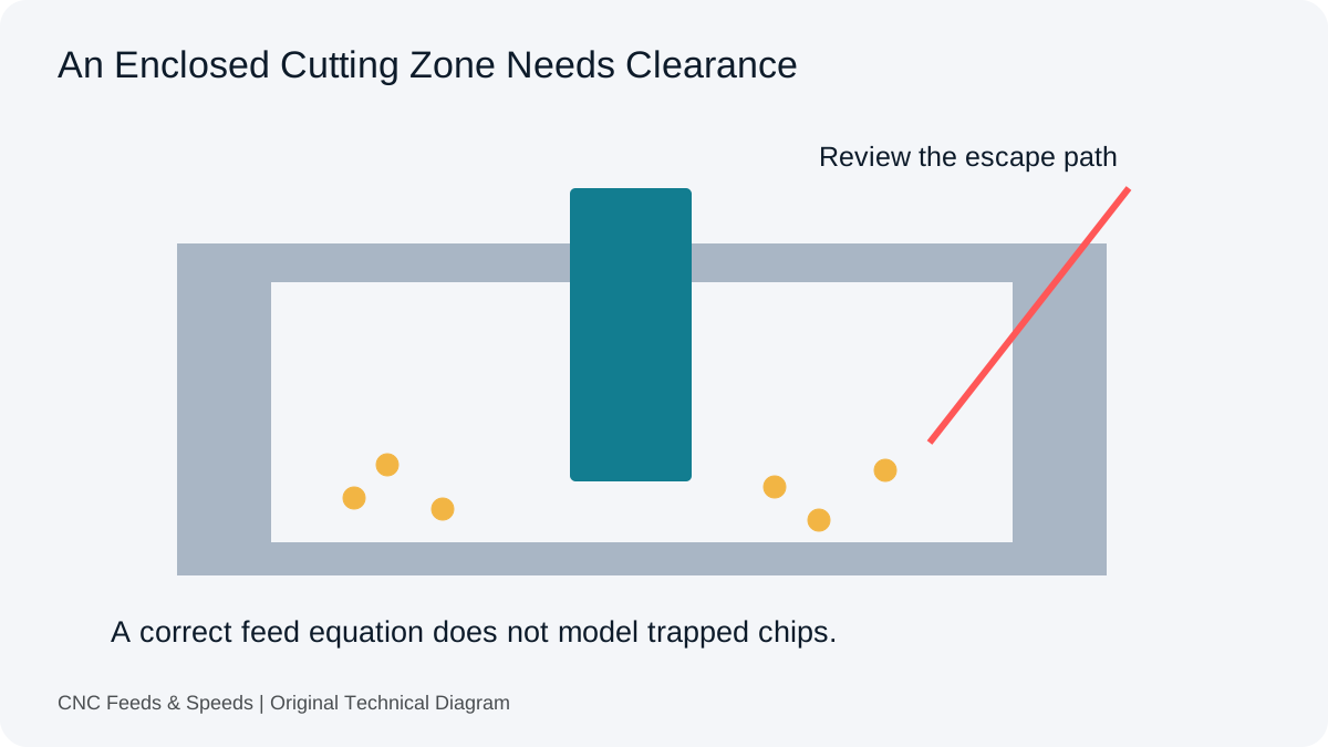
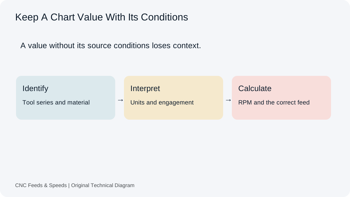
A carbide drill speed and feed reference should identify the drill series, material condition, diameter range and applicable hole depth. Keep any coolant and depth-ratio instructions with that source. A generic carbide label does not establish which speed or feed belongs to a particular drill, and the RPM formula contains no model of chip evacuation or coolant access.
What The Calculation Leaves To The Process
The panels do not select a peck cycle, point geometry, hole tolerance or through-tool coolant arrangement. Use the drilling reference for the preparation questions and the cutting chart guide for source definitions. Record actual RPM, feed, drill identifier and hole result together so a later setup can be compared with the same conditions.
A drawing may specify cylindrical hole depth while the program locates the drill tip. Check that distinction before estimating travel. The tools below separate ideal point geometry, chamfer depth and boring stock from the feed calculation above. They do not choose a clearance, tool offset or machine cycle.
Drill Point And Breakthrough
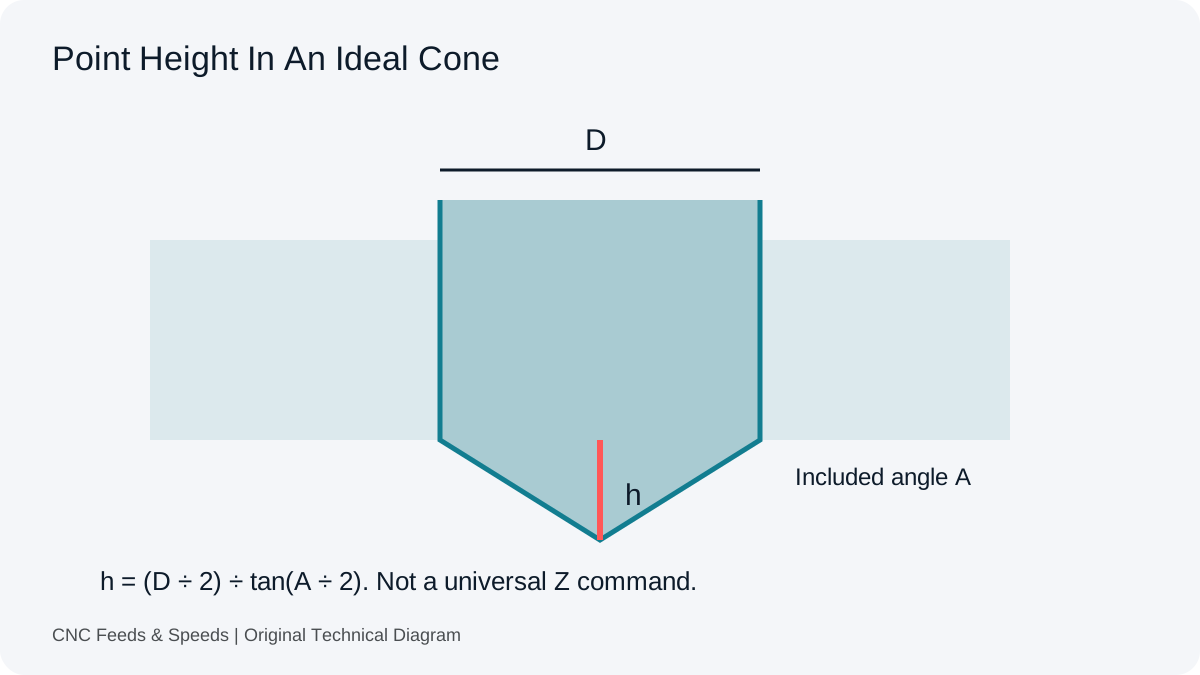
Find the length of an ideal conical drill point from diameter and included angle. Add it to a specified cylindrical depth to inspect tip travel. Treat split points, chisel edges and breakthrough clearance as separate checks against the actual drill and job.
Open Drill Point Tool
Point length = diameter ÷ (2 × tan(included angle ÷ 2)). A 10 mm diameter and 90 degree ideal point give 5 mm of point length. A required 20 mm cylindrical depth then corresponds to a 25 mm tip depth from the entry surface, before any additional clearance.
Drill Point And Tip Depth
Enter the values you know. The result is calculated in your browser.
Calculation only. Verify toolmaker data, material grade, engagement, machine limits, workholding and actual cutting conditions before production.
The angle is the full included angle, not the half angle used in the tangent. The tip-depth result is a geometric distance from the entry surface. It is not a signed Z command or a complete breakthrough instruction.
Convert a major diameter, an existing hole or flat-tip diameter, and an included cone angle into ideal axial depth. Keep the radial chamfer width distinct from axial travel. Locate the actual tool contact and offset before transferring this geometric difference into a program.
Open Chamfer Depth Tool
Axial depth = (major diameter − minor diameter) ÷ (2 × tan(included angle ÷ 2)). Increasing a 6 mm opening to a 10 mm major diameter with a 90 degree cone requires 2 mm of ideal axial depth and creates a 2 mm radial width.
Chamfer And Countersink Geometry
Enter the values you know. The result is calculated in your browser.
Calculation only. Verify toolmaker data, material grade, engagement, machine limits, workholding and actual cutting conditions before production.
Enter zero for the minor diameter only when measuring from a theoretical sharp apex. For an existing hole, enter its actual diameter. A tool’s flat tip, edge radius or a different drawing convention can change the contact datum.
Separate the change in bore diameter from the radial stock removed. Estimate an ideal annular volume for a stated axial length. Total radial stock is not an instruction to remove it in one pass, and the tool does not select an allowance or predict bore accuracy.
Open Boring Stock Tool
Radial stock = (finished diameter − initial diameter) ÷ 2. Ideal removed volume = π × (finished diameter² − initial diameter²) × length ÷ 4. Enlarging an 18 mm hole to 20 mm removes 1 mm radially; over 30 mm, the ideal volume is about 1,790.71 mm³.
Boring Radial Stock And Volume
Enter the values you know. The result is calculated in your browser.
Calculation only. Verify toolmaker data, material grade, engagement, machine limits, workholding and actual cutting conditions before production.
This annular model assumes straight, concentric cylindrical holes. It excludes tapers, an interrupted initial hole, chamfers, spring passes and dimensional changes after machining. Inspect the actual prepared hole before choosing a pass sequence.
Use the cutting diameter and supplier cutting speed to inspect boring RPM. Establish the actual spindle setting before multiplying it by feed per revolution. The bore diameter belongs in the speed calculation; the boring bar shank diameter describes a different part of the setup.
Open Boring Speed Tools
Metric RPM = 1000 × cutting speed ÷ (π × cutting diameter). At an illustrative 100 m/min and 20 mm cutting diameter, the result is about 1,591.55 RPM. At an actual 1,500 RPM and an independently selected 0.10 mm/rev, the matching linear feed is 150 mm/min.
Boring RPM From Source Speed
Enter the values you know. The result is calculated in your browser.
Calculation only. Verify toolmaker data, material grade, engagement, machine limits, workholding and actual cutting conditions before production.
Boring Feed From Actual RPM
Enter the values you know. The result is calculated in your browser.
Calculation only. Verify toolmaker data, material grade, engagement, machine limits, workholding and actual cutting conditions before production.
For single point boring, retain the supplier feed per revolution directly. Multi-edge tooling may define effective cutting teeth differently. Verify the supplier’s convention, bar reach, alignment and available clearance before applying the values.
The point and chamfer relationships come from the right triangle formed by a cone’s radius and half included angle. The boring stock relationship comes from the difference in hole radii. These independent geometric checks do not model chip evacuation, cutting forces or chatter. Use the peck travel guide when repeated retracts change the travel history.
For a primary operation reference, Sandvik Coromant’s boring definitions explain cutting diameter, feed and radial depth. The reaming workspace keeps a separate workflow for a prepared hole and reamer rather than treating the two processes as interchangeable.
Drilling Questions
Does The Second Panel Calculate Linear Feed From A Source Feed Per Revolution?
The second main panel divides entered linear feed by actual RPM. Use the Drill Linear Feed quick tool to calculate forward from RPM and source feed per revolution.
Should I Use Drill Diameter Or Hole Depth In The RPM Formula?
Use drill cutting diameter. Hole depth affects the process and supplier instructions, but it is not the diameter term in the RPM equation.
Can A Milling Feed Calculator Replace This Workflow?
Only if the source convention is interpreted correctly. The usual drill feed-per-revolution calculation has no extra flute-count multiplier. Keep the drilling convention with the result.
Help Improve This Resource
Request A Tool
Describe the calculation your workflow needs, the inputs you already have and the output you want to check. Include units and an example without confidential job details.
Share this page address, the entered values and the result you expected. Include the source of your comparison so the formula, units and explanation can be investigated.
The site brings calculation tools and machining references into one workspace. Use the editorial and site information to understand its purpose and limitations. Send corrections with a reproducible example through the error report form.
Related Articles
Continue with the calculation, setup or troubleshooting question closest to your task.
When A Router Cannot Run Slowly Enough To Drill
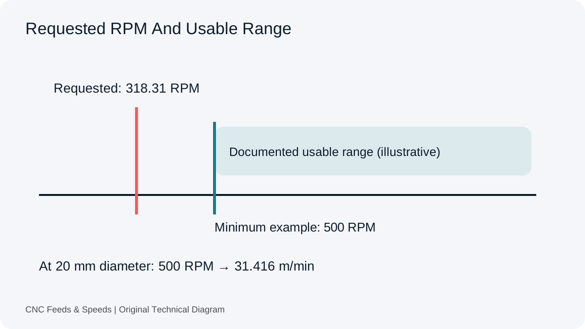
Compare drill requirements with the usable spindle range. Calculate achieved cutting speed without treating feed adjustment as a cure for incompatible tooling.