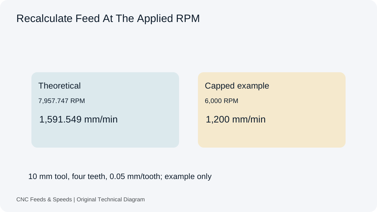
Nominal milling feed per tooth is linear feed divided by actual spindle RPM and effective cutting teeth. It lets you inspect the tooth-feed value implied by a saved program. Maximum chip thickness also depends on engagement and cutter geometry, so those two quantities should not be treated as identical.
Definition
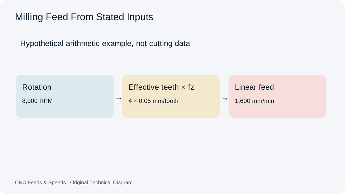
For a milling cutter, chip load per tooth can be calculated as fz = F ÷ (RPM × Z). In the opposite direction, F = RPM × Z × fz. This makes chip load a bridge between the cutting condition and the programmed feed. A four-flute cutter and a two-flute cutter cannot use the same feed at the same RPM and chip load because their tooth counts are different.
Why chip load matters
The chip needs to have enough thickness to carry heat away from the cutting edge rather than rubbing the material. If the chip is too thin for the tool and engagement, rubbing and heat can become dominant. If the chip is too heavy for the setup, tool load and deflection can increase. The appropriate starting value is therefore a tool- and material-specific input, not something an online calculator should invent.
A worked example
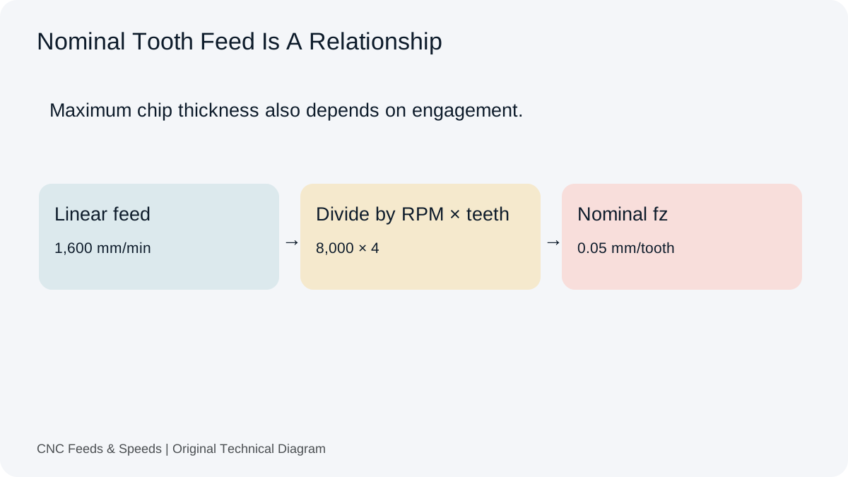
At 8,000 RPM, a 4-flute cutter with 1,600 mm/min feed has fz = 1,600 ÷ (8,000 × 4) = 0.05 mm/tooth. To reverse the calculation, use the same equation: 0.05 × 8,000 × 4 = 1,600 mm/min. The reciprocal checks are useful during program review because they expose unit mistakes quickly.
Flute count and effective cutting edges
The flute count used in a formula should reflect the cutting geometry assumed by the data source. An end mill with four physical flutes has four edges, but some specialized cutters are used under conditions where not every edge behaves identically. Follow the tooling documentation rather than simplifying all tools to a generic tooth count.
Engagement and chip thinning
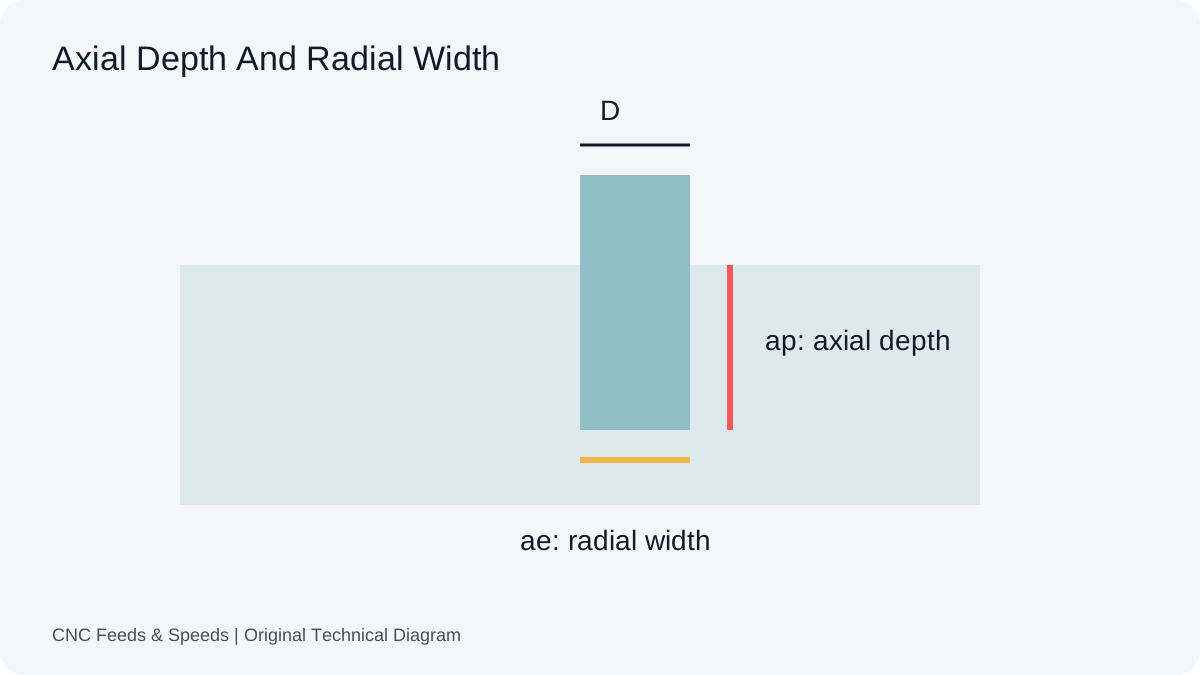
Radial engagement changes the chip geometry. In certain low-radial-engagement strategies, the cutter may require a chip-load adjustment so the edge sees sufficient chip thickness. The adjustment should come from a sound machining reference or toolmaker method. The basic chip-load calculator should remain a transparent arithmetic tool rather than hiding an unverified correction factor.
Chip load is not tool life
A correct chip-load relationship does not tell you whether a tool will last the required number of minutes or parts. Tool life also depends on cutting speed, material hardness, coolant, edge preparation, runout, stick-out and the distribution of the load through the cut. This is why the best setup records preserve both calculated values and actual observations.
Using chip load during troubleshooting
If the cutter is rubbing, inspect the physical symptoms first: unusually fine dust-like chips, heat, poor finish, or excessive edge wear. If the load is too high, watch for overload alarms, deflection, burrs or accelerated wear. Change one major parameter at a time and keep the source values and resulting observations together in the setup sheet.
Metric and imperial chip-load units
Metric chip load is commonly expressed in mm/tooth; imperial values are commonly in inches/tooth. The calculator’s unit toggle is there to keep the arithmetic internally consistent. Converting only the final feed number is not enough if RPM or chip-load units were mixed earlier in the calculation.
Cross-checking a chart
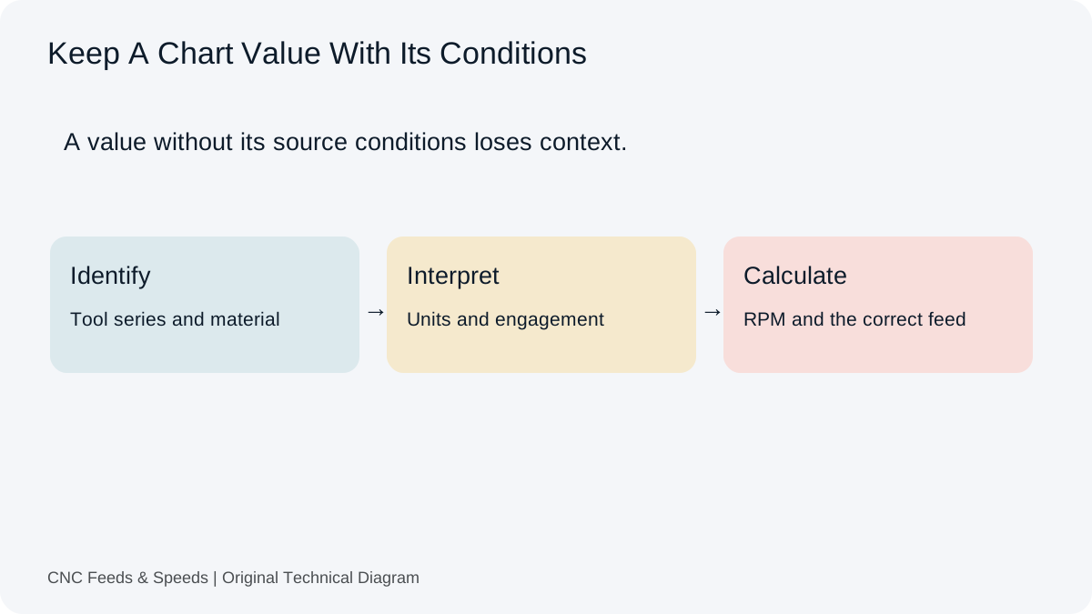
When a toolmaker chart gives cutting speed and chip load, calculate RPM from cutting speed and diameter, then calculate feed from RPM, flute count and chip load. That two-step process lets you compare the chart’s intended values with the values in a CNC program. Any mismatch should be traced to units, tool geometry, diameter, or the version of the cutting table used.
Has Chip Thinning Already Been Accounted For?
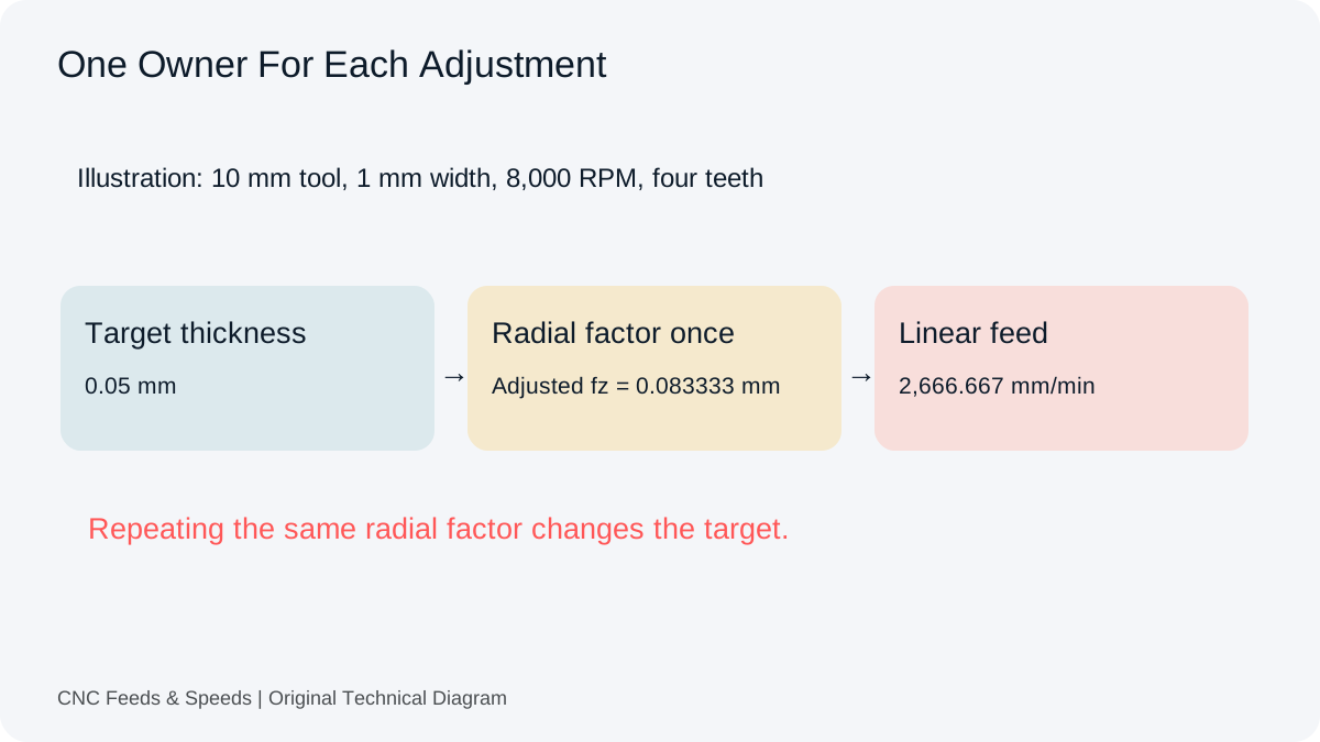
Nominal feed per tooth and maximum chip thickness describe different quantities. At light radial engagement, a cylindrical cutter with a 90 degree entering angle can produce a thinner maximum chip than the nominal tooth feed suggests. The new radial chip-thinning check separates the target thickness from the adjusted tooth feed.
Before you apply a multiplier, establish what the supplier value represents and whether CAM has already adjusted the programmed feed. A calculator result that includes compensation should not receive the same adjustment again. Verify the current CAM documentation for the operation rather than assume that a similarly named setting behaves identically in every product.
Read The Factor Within Its Domain
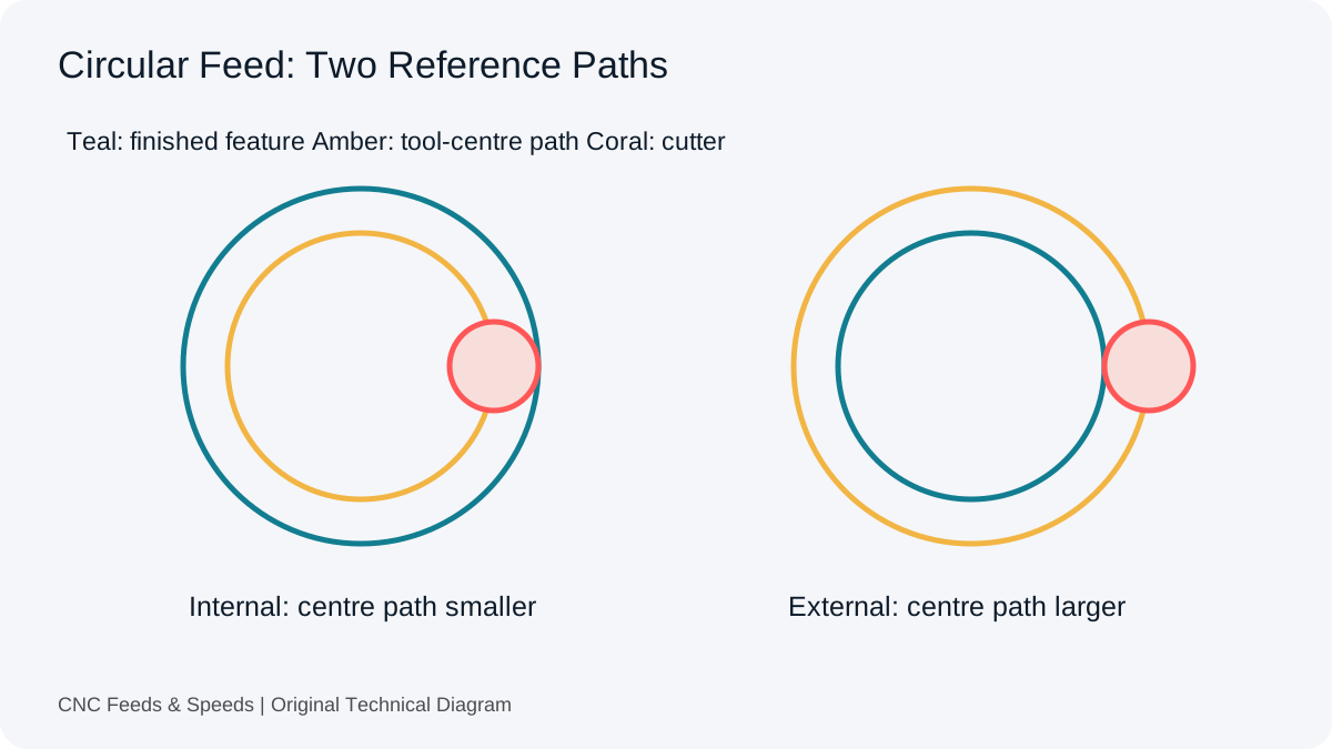
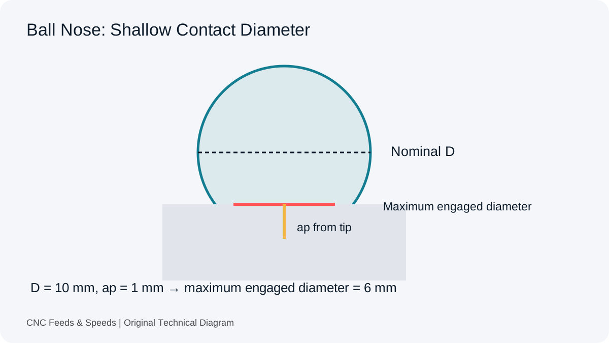
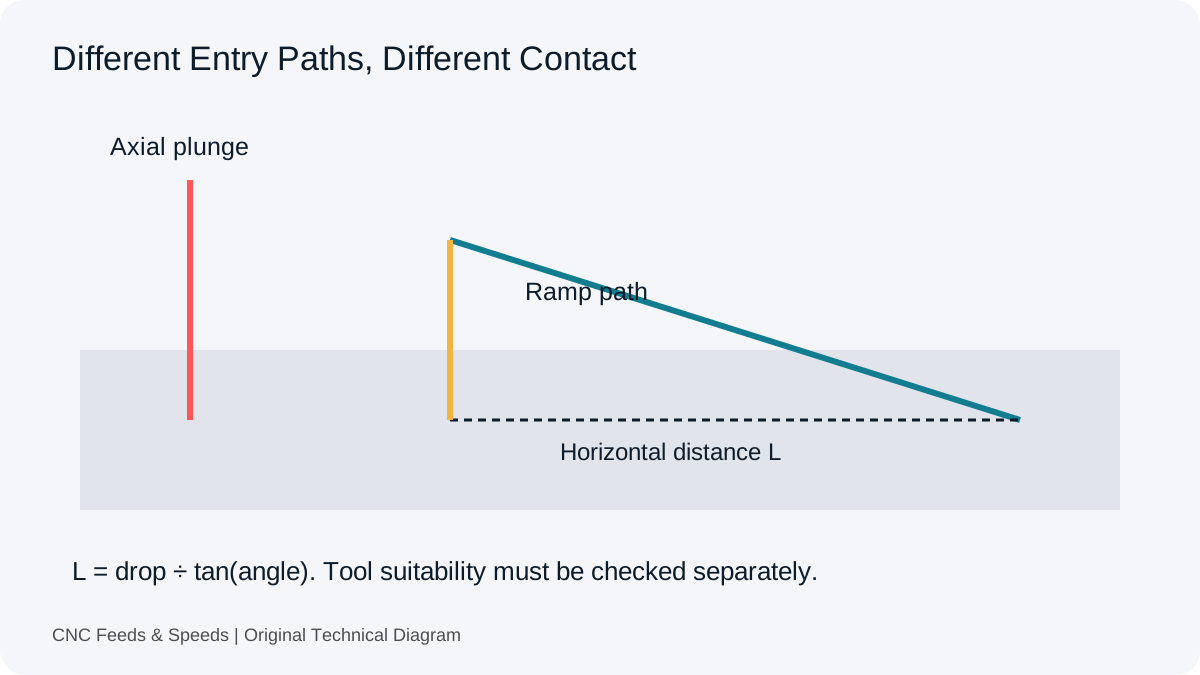
For this radial-only model, the factor returns to one at half-diameter engagement and remains one above it. It does not rise again toward a full slot. Ball nose tools, round inserts, entry moves and changing corner engagement require separate treatment, so a factor alone does not establish a suitable milling strategy.
The Harvey Performance chip-thinning explanation provides toolmaker context. Use it to understand the distinction, then obtain the appropriate target thickness for your actual tool and cut. Keep compensation status in your saved setup so another reader can see how the final feed was obtained.
Frequently asked questions
What is chip load per tooth?
It is the feed distance attributed to one cutting edge per tooth engagement. For milling it is commonly calculated as feed divided by RPM and flute count.
Does more flutes always mean more feed?
At the same RPM and chip load, the arithmetic feed increases with flute count. The actual usable value still depends on tool geometry, chip evacuation, material and engagement.
Can chip load be used for drilling or tapping?
Those operations normally use different data conventions, such as feed per revolution or thread pitch. Use the calculation that matches the operation.
Applications And Related Calculation Workflows
Checking Chip Load From An Existing Program
Divide programmed milling feed by actual RPM and effective teeth to recover nominal feed per tooth. That gives a useful audit value when a spindle setting changes or a program is transferred between machines. It does not establish maximum chip thickness through every engagement. Use the chip load calculator to reproduce the arithmetic before comparing the toolmaker conditions.
Further study: Sandvik Coromant tooth-feed and chip-thickness definitions. Compare the stated engagement and geometry before treating nominal feed per tooth as maximum chip thickness.
Help Improve This Resource
Request A Tool
Describe the calculation your workflow needs, the inputs you already have and the output you want to check. Include units and an example without confidential job details.
Request A ToolReport An Error
Share this page address, the entered values and the result you expected. Include the source of your comparison so the formula, units and explanation can be investigated.
Report An ErrorCNC Feeds & Speeds Editorial Desk
The site brings calculation tools and machining references into one workspace. Use the editorial and site information to understand its purpose and limitations. Send corrections with a reproducible example through the error report form.