A ball nose end mill can run at the expected spindle RPM and still cut at a much lower surface speed than the nominal diameter suggests. Shallow contact uses only part of the spherical end. The first check is therefore the diameter actually engaged, not an automatic increase in feed or spindle speed.
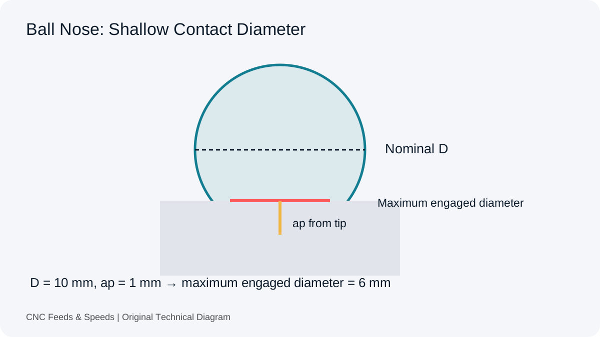
Nominal Diameter Does Not Describe Every Contact
A 10 mm ball nose has a 10 mm nominal diameter at its equator. A shallow horizontal cut near the tip does not reach that equator. At a contact depth of 1 mm from the tip, the maximum engaged diameter is only 6 mm. Surface speed varies along the contact, and the exact rotational centre still has zero surface speed. One diameter value cannot make every point on the ball behave like a cylindrical edge.
Use the ball nose contact-diameter tool for the specific untilted geometry it describes. Its depth is measured from the tip, not from an arbitrary stock surface or a toolpath origin. Before calculating, establish where the tool actually touches the part and whether the surface can reasonably be represented by that model.
Derive The Contact Diameter
For nominal diameter D and axial contact depth ap, the spherical cross-section gives Deff = 2 × √(ap × (D − ap)). This is equivalent to √(D² − (D − 2ap)²). The tool on this site accepts depths greater than zero and no more than D/2. That restriction avoids applying a shallow-contact equation beyond the equator and reporting an incorrectly shrinking maximum diameter.
For D = 10 mm and ap = 1 mm, Deff = 2 × √(1 × 9) = 6 mm. At ap = 5 mm, Deff becomes the full 10 mm diameter. A zero depth gives zero contact diameter and does not provide a finite RPM solution for a positive target surface speed. The calculator rejects that case rather than display an infinite or apparently usable spindle command.
What The RPM Calculation Actually Means
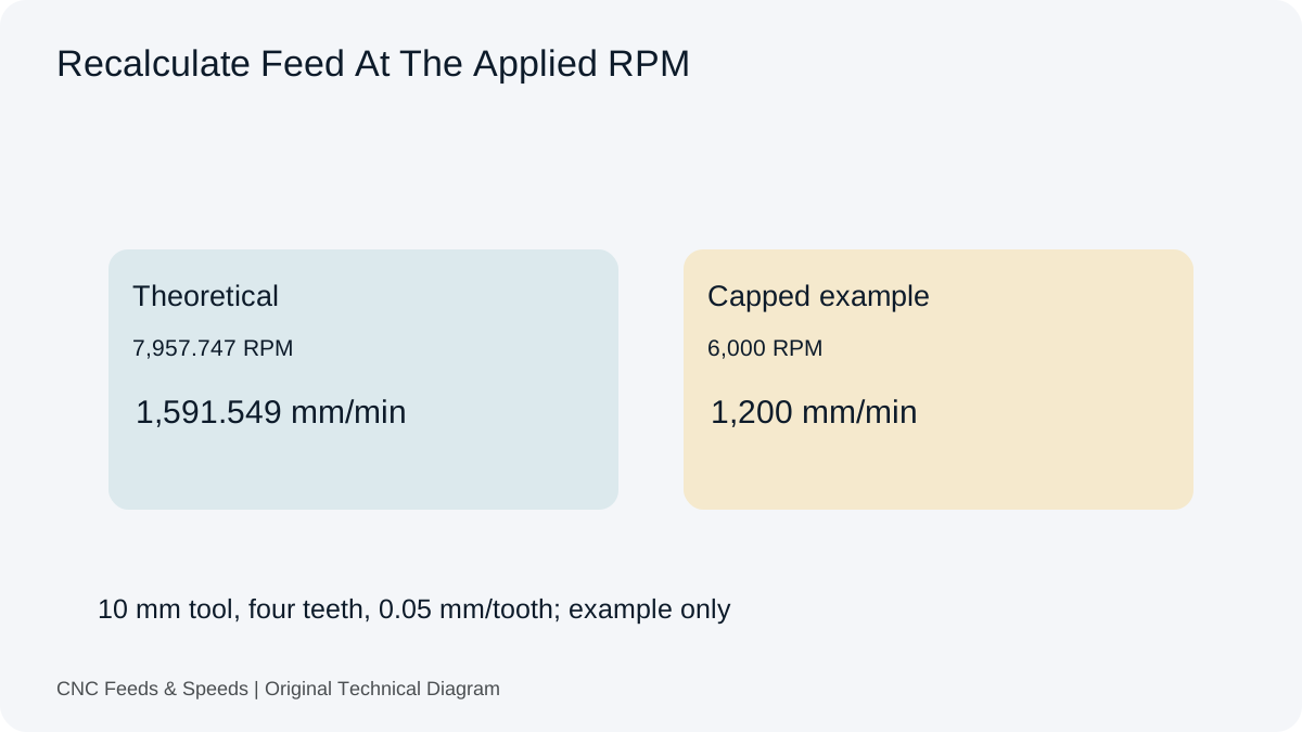
Suppose the hypothetical target cutting speed is 150 m/min. Using the 6 mm engaged diameter gives RPM = 1,000 × 150 ÷ (π × 6), or approximately 7,957.747 RPM. Using the nominal 10 mm diameter would give about 4,774.648 RPM. Those are different arithmetic results because the diameter in the equation is different. Neither number establishes that the chosen tool should run at that condition.
If the machine ceiling is 6,000 RPM, achieved cutting speed at the 6 mm maximum engaged diameter becomes about 113.097 m/min. The calculator shows the capped command and the achieved speed separately. That result still does not describe the speed at every point of contact. Our surface-speed explanation is useful when the distinction between rotation and linear cutting speed becomes unclear.
Why Feed Should Not Be Increased Automatically
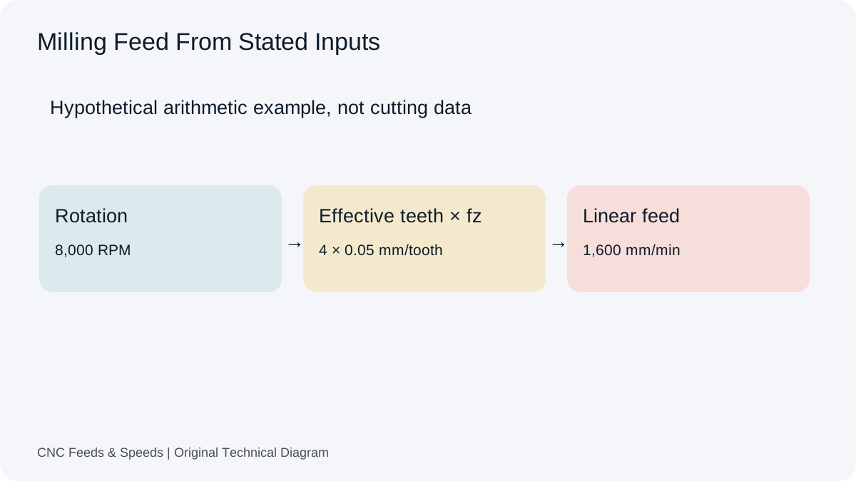
A smaller effective diameter can suggest a higher RPM to preserve a specified surface speed, but a feed decision still needs the toolmaker’s guidance for the actual engagement. Edge geometry, contact near the tip, runout and finishing conditions matter. Increasing RPM and then multiplying by a generic tooth-feed value may create a number unsupported by the intended tool application.
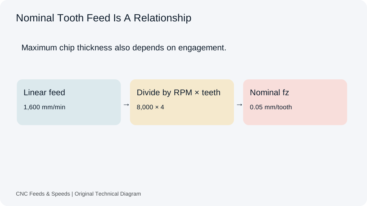
Keep nominal tooth feed separate from maximum chip thickness. The chip-load guide explains why those quantities are not always interchangeable. Ball nose geometry is not covered by the site’s cylindrical radial-only chip-thinning tool. Combining the two outputs would create an undocumented model, even if every individual equation appears mathematically familiar.
Inclined Surfaces Need A Different Description
A tool tilted relative to the surface can move the cutting zone away from the centre. A surface that changes slope can also change the region of the ball in contact without any change in nominal tool diameter. The simple horizontal, untilted cross-section no longer describes the full situation. Do not enter a convenient depth merely to force an answer from the calculator.
Harvey Performance’s ball nose strategy guide distinguishes contact conditions and tilted geometry. Use the appropriate manufacturer method for the tool and surface. A general diagram can clarify the concept, but it cannot supply an unmeasured contact angle or guarantee a finish on a changing three-dimensional surface.
Diagnose A Finish Problem Before Changing Everything
Begin with the feature and toolpath. Identify whether the issue appears on flat areas, steep walls, transitions or the whole surface. Then inspect tool condition, runout, stickout, holder cleanliness and workpiece support. A finish defect that follows a geometry transition deserves a contact review; a defect caused by a damaged edge will not be solved by a more precise diameter calculation.
Record any change to speed, feed, stepover or tool orientation separately. If several variables change at once, a better finish does not reveal which change helped. Scallop height, contact geometry and dynamic stability are different questions. This article does not calculate scallop or predict surface roughness, and the diameter tool should not be described as a surface-finish optimiser.
A Real Question About Changing Contact
An Autodesk feature discussion about ball-end finishing describes the difficulty of moving between tip and side engagement. A later reply raises the practical question of spindle acceleration. The discussion identifies a real workflow problem, but its proposed automatic solution is not a validated prescription for every machine or a statement of current Fusion functionality.
Our bounded calculation addresses the first part of that problem: identify the maximum diameter for one defined contact. It does not attempt to command a spindle dynamically through a three-dimensional path. When the machine cannot reach the theoretical result, review the relationship between spindle limits and feed before carrying a number into CAM.
What To Preserve With The Result
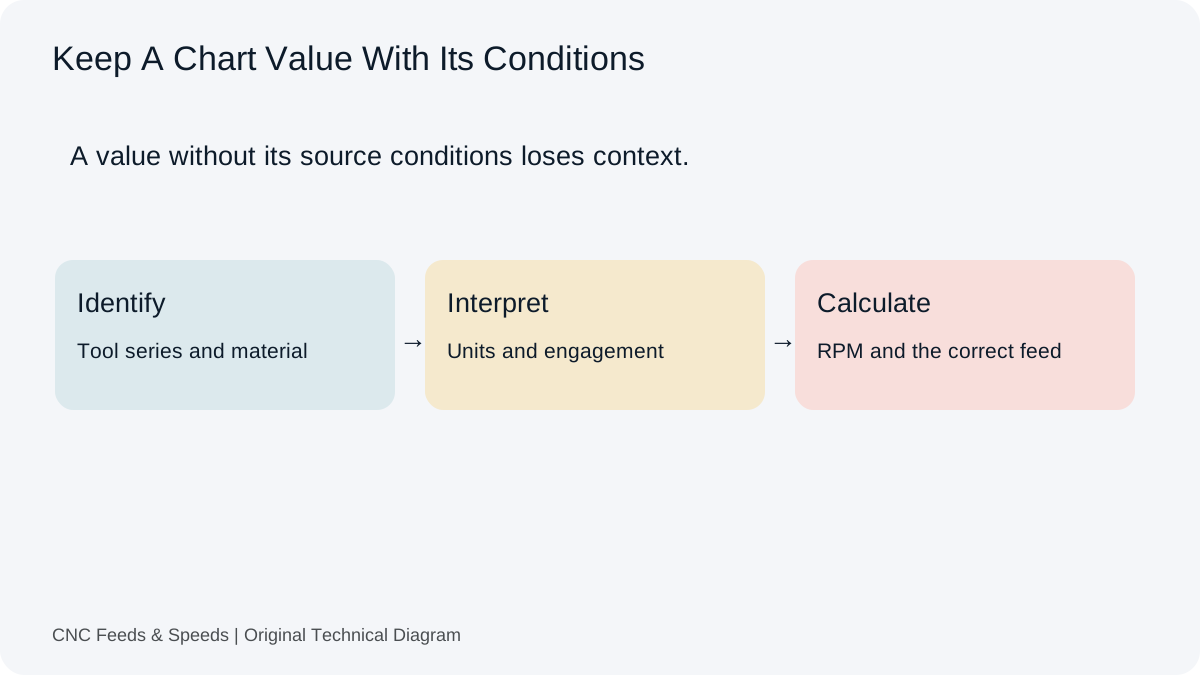
Save the nominal tool diameter, contact depth definition, surface orientation, requested cutting speed, applied RPM and toolmaker source. Add the actual toolpath strategy and observed result to the job record. A later reader should be able to distinguish a geometric estimate from a condition checked on the machine. The setup-record guide provides a way to retain those distinctions without building a misleading universal recipe.
Ball Nose Questions
Does Effective Diameter Remove The Zero-Speed Tip?
No. It describes a maximum engaged diameter under a stated geometry. The exact centre of the ball still has zero rotational surface speed.
Can I Enter A Depth Greater Than Half The Diameter?
Not in this tool. It is deliberately limited to shallow contact up to the equator. Deeper or different contact needs another correctly defined model.
Is The Diagram A Machining Recommendation?
No. It explains geometry. Select cutting data for the actual tool, material, contact and machine before planning a cut.
Help Improve This Resource
Request A Tool
Describe the calculation your workflow needs, the inputs you already have and the output you want to check. Include units and an example without confidential job details.
Request A ToolReport An Error
Share this page address, the entered values and the result you expected. Include the source of your comparison so the formula, units and explanation can be investigated.
Report An ErrorCNC Feeds & Speeds Editorial Desk
The site brings calculation tools and machining references into one workspace. Use the editorial and site information to understand its purpose and limitations. Send corrections with a reproducible example through the error report form.