Hole depth divided by feed estimates only a defined amount of feed travel. A peck cycle can add retracts, repeated approaches, dwell and a final return. Before a time estimate is used for planning, identify those motions and establish which ones the calculator or CAM estimate has included.
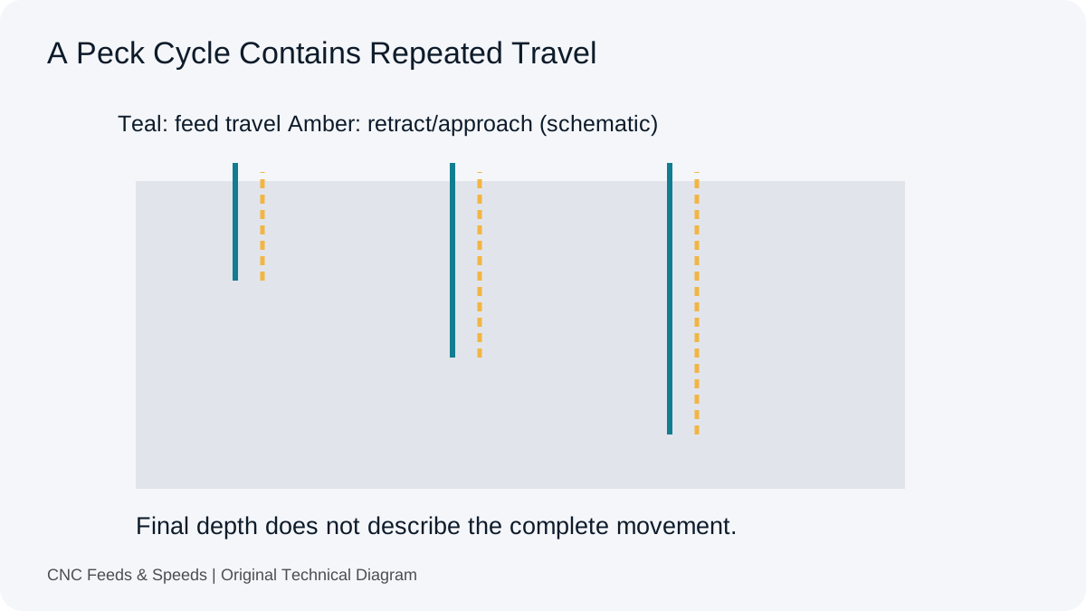
A Depth Is Not A Motion History
A 30 mm hole does not describe how the drill reached the bottom. The cycle may feed continuously, break chips through small retracts or return to a clearance plane after successive increments. It may approach a previous depth quickly and then feed through an allowance before cutting new material. Those choices change total travel and the time spent at different rates, even when the final depth and source cutting feed stay the same.
A user in an Autodesk discussion about large drill retracts describes repeated travel above a previous peck as a cycle-time problem. That is a useful reason to inspect the actual sequence. It is not evidence that every post or controller has the same retract behaviour, or that removing an allowance would be an appropriate correction for another job.
Define The Cutting Feed First
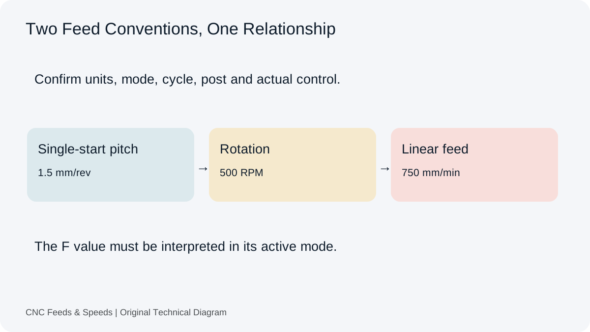
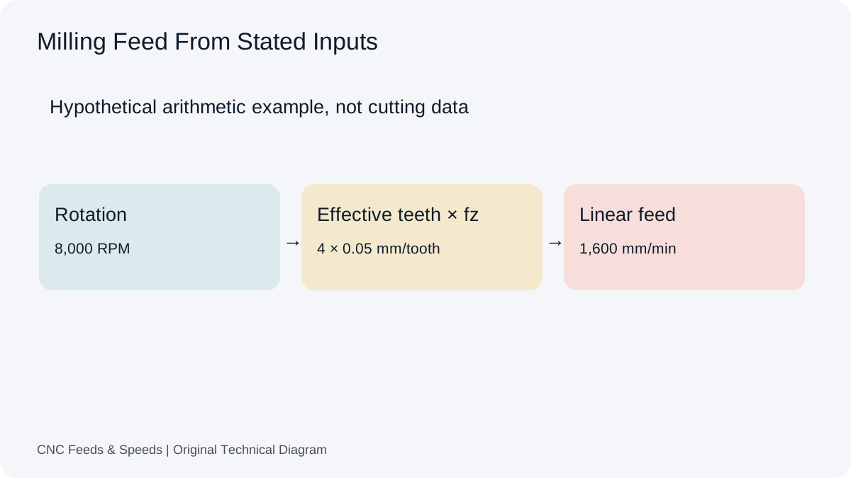
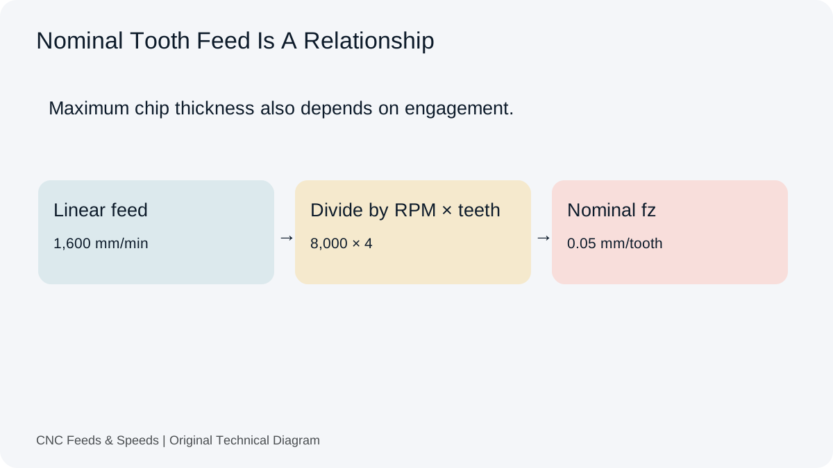
A drilling source may state feed per revolution rather than millimetres per minute. Multiply the verified feed per revolution by actual RPM to obtain linear feed. For example, 0.15 mm/rev at 2,000 RPM gives 300 mm/min. The drilling workspace includes that forward relationship and a reverse check. Neither operation chooses a peck depth or a chip-breaking strategy.
At 300 mm/min, 30 mm of new cutting travel takes 0.1 minute, or six seconds, under the constant-feed assumption. That is a useful component of the estimate. It is not yet a complete peck-cycle time, and it does not include drill-point allowance, approach, dwell or a return plane. Write exactly what the 30 mm represents before adding more terms.
Build A Motion Ledger
Separate new cutting travel from repeated feed travel. Then list rapid retracts, rapid approaches, dwell and the final return. Use a documented feed or assumed rapid rate for each category, and label the assumption. A simple ledger is easier to inspect than a single correction percentage because another reader can see which movement has been included and which remains unknown.
Suppose the hypothetical sequence contains the six seconds of new cutting above and 120 mm of additional rapid travel. At an assumed constant rapid rate of 6,000 mm/min, that additional distance contributes 1.2 seconds. The subtotal is 7.2 seconds before acceleration, deceleration, dwell, spindle events or other movement. It is a component estimate, not a prediction that the machine will finish the cycle in 7.2 seconds.
| Component | Assumption | Time |
|---|---|---|
| New cutting | 30 mm at 300 mm/min | 6 s |
| Extra rapid travel | 120 mm at constant 6,000 mm/min | 1.2 s |
| Known subtotal | Excludes acceleration, dwell and other events | 7.2 s |
Rapid Rate Is Not Necessarily Achieved Rate
Short retracts may not give an axis enough distance to reach its nominal rapid velocity. The control can also apply motion limits and positioning behaviour that a distance/rate calculation does not model. This matters most when many short moves are repeated. Adding their distances and dividing by a headline machine rapid rate can produce an optimistic estimate without any arithmetic error.
Use the constant-feed time calculator only for the travel segments it describes. If you estimate a rapid component separately, preserve its rate assumption and exclusions. Our cycle-time guide explains how a component estimate differs from CAM time, a measured machine cycle and a production quote.
Read The Cycle Parameters In Their Own Context
Peck increments, minimum increments, chip-break distances, clearance planes and re-entry allowances can have controller-specific meanings. A familiar letter in a canned cycle is not enough to establish the motion. Read the current machine documentation and the post-processor output together. Do not transfer a code example between controls merely because the operation is described as peck drilling in both systems.
Autodesk’s drilling-cycle reference distinguishes the available cycle concepts and their parameters. It is useful for understanding what must be checked in a CAM workflow. The operation still depends on the target post and control, and the drill supplier determines whether the proposed cycle is suitable for that tool and material.
Do Not Add Pecking As A Default Cure
Pecking is not automatically the correct response to every deep hole or evacuation concern. Drill design, hole-depth ratio, material and coolant delivery can change the appropriate method. A tool intended for a particular through-coolant cycle may have instructions that differ from a general workshop rule. The time estimate should follow the selected process, rather than select the process simply because its time is easy to calculate.
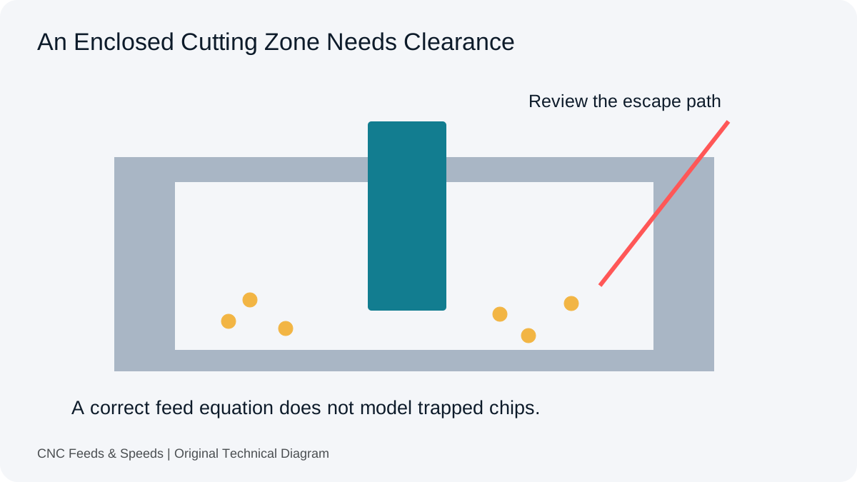
If chips are packing, investigate the mechanism before shortening or lengthening increments. Record the exact tool, depth, material, coolant access and observed chips. The chip-evacuation guide distinguishes an obstruction problem from a feed arithmetic problem. Its milling examples do not replace drill-specific instructions, but the evidence-first approach applies to both situations.
Breakthrough And Final Return Are Separate Events
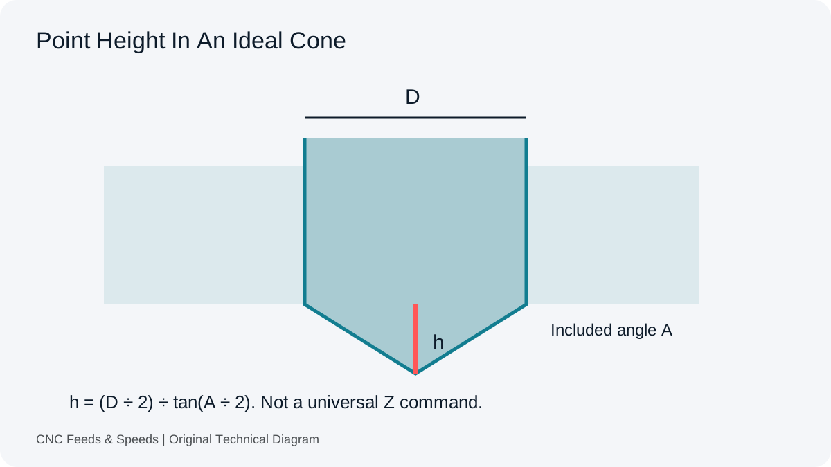
Full-diameter breakthrough can require tip travel beyond the nominal material thickness. A final retract can also return to a different plane from the intermediate pecks. These are independent additions to the motion budget. A hole depth copied from a drawing may describe cylindrical depth, tip depth or another datum, so establish that definition before calculating the last increment.
The drill-point allowance explanation separates simple point geometry from a machine-ready depth command. Include the applicable geometry and any verified allowance in the ledger. Do not add an arbitrary extra depth to every hole; nearby fixtures, an angled exit or a blind-hole requirement can change what is permitted.
Compare Estimate And Observation Deliberately
When an actual cycle is available, measure the same start and end events used in the estimate. A time that includes spindle start should not be compared without explanation to one that begins at the first feed move. Keep the machine, control, post version and cycle settings with the observation. A discrepancy then becomes evidence about a missing component, rather than a reason to apply an unexplained multiplier to every future hole.
Peck-Time Questions
Can I Multiply A Single-Peck Time By The Number Of Pecks?
Only if that model truly represents each movement. Peck lengths, returns and reapproach distances may change through the cycle, so inspect the sequence first.
Does Hole Depth Include The Drill Point?
Not necessarily. Establish the drawing and CAM depth definition. Cylindrical depth and tip travel are different quantities.
Is The Estimate Suitable For A Production Quote?
Use it as one documented component. A quote needs the actual scope, cycle assumptions, handling and other production requirements.
Help Improve This Resource
Request A Tool
Describe the calculation your workflow needs, the inputs you already have and the output you want to check. Include units and an example without confidential job details.
Request A ToolReport An Error
Share this page address, the entered values and the result you expected. Include the source of your comparison so the formula, units and explanation can be investigated.
Report An ErrorCNC Feeds & Speeds Editorial Desk
The site brings calculation tools and machining references into one workspace. Use the editorial and site information to understand its purpose and limitations. Send corrections with a reproducible example through the error report form.