A side-cutting feed is not automatically a suitable plunge or ramp feed. The direction of motion changes which edges cut, how chips escape and what loads the tool sees. Before entering a percentage into CAM, establish whether the cutter can perform the intended entry and obtain guidance for that operation.
Three Fields, Three Different Tasks
Cutting feed often describes the command used during a main machining pass. Plunge feed describes an axial entry in the operation’s coordinate system. Ramp feed applies while depth changes along a linear or circular path. The exact field names and behaviour depend on CAM and the post. Read those definitions instead of assuming that each field is another label for the same linear rate.
A Carbide 3D beginner discussion includes a direct question about whether ramp feed should be a percentage or remain unchanged. The question is understandable, but there is no single percentage that answers it for every tool. Entry geometry and the tool’s supported use come before a numerical shortcut.
Check The Cutter Before The Feed
An end mill’s ability to cut along its side does not establish that it can plunge into solid material. Tool construction, centre-cutting capability, edge geometry and chip space matter. A drill and an end mill are not interchangeable entry tools. A cutter can also be capable of some ramping conditions while remaining unsuitable for another angle, depth or material.
Harvey Performance’s tool-entry explanation distinguishes several entry methods and discusses the special demands of a straight plunge. Its application context matters. Treat any published starting suggestions as manufacturer guidance for their stated conditions, rather than turn a general article into a rule for every cutter in the shop.
A Linear Ramp Needs Room
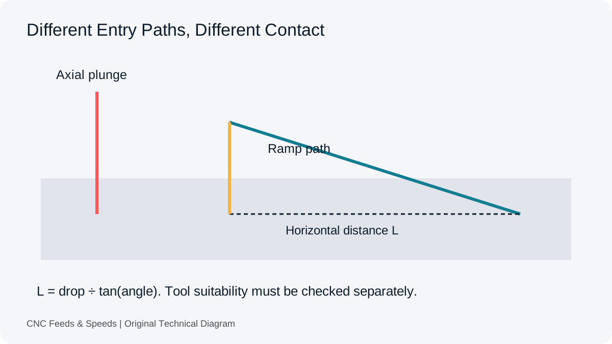
A ramp angle relates the axial drop to horizontal travel. For an ideal straight ramp, horizontal distance L = drop ÷ tan(angle). A 2 mm drop at three degrees needs approximately 38.162 mm of horizontal travel. That number describes geometry only. It does not establish that the tool can ramp at three degrees or that the part has enough clearance for the complete cutter and holder.
A shorter pocket may tempt a steeper angle to make the path fit. That is a process change. Check the tool’s permitted ramping conditions and the CAM path. Include any reversal or transition at the end. An adequate centreline distance is not the same as adequate swept-tool clearance. The diagram in this article deliberately separates the dimensions so the geometric requirement can be inspected.
A Helix Needs A Clearly Defined Diameter
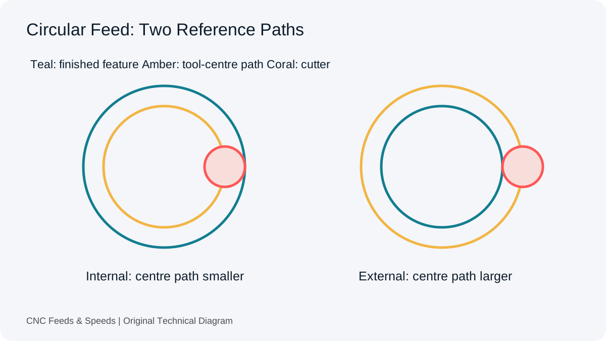
For a circular ramp, distinguish finished feature diameter from tool-centre path diameter. A 10 mm centre-path diameter has a circumference of π × 10 mm. If the tool descends 1 mm per revolution, the path angle is arctan(1 ÷ (π × 10)), or about 1.823 degrees. The corresponding three-dimensional centre-path length is about 31.432 mm per revolution.
Using a finished hole diameter in place of the centre-path diameter changes that calculation. A cutter occupies space inside the feature, so the two dimensions are not normally identical. Our circular-feed guide explains the planar path distinction. It does not provide a complete helical-feed conversion, and its tool should not be used as though axial motion were absent from a ramp.
Why A Percentage Can Hide Missing Information
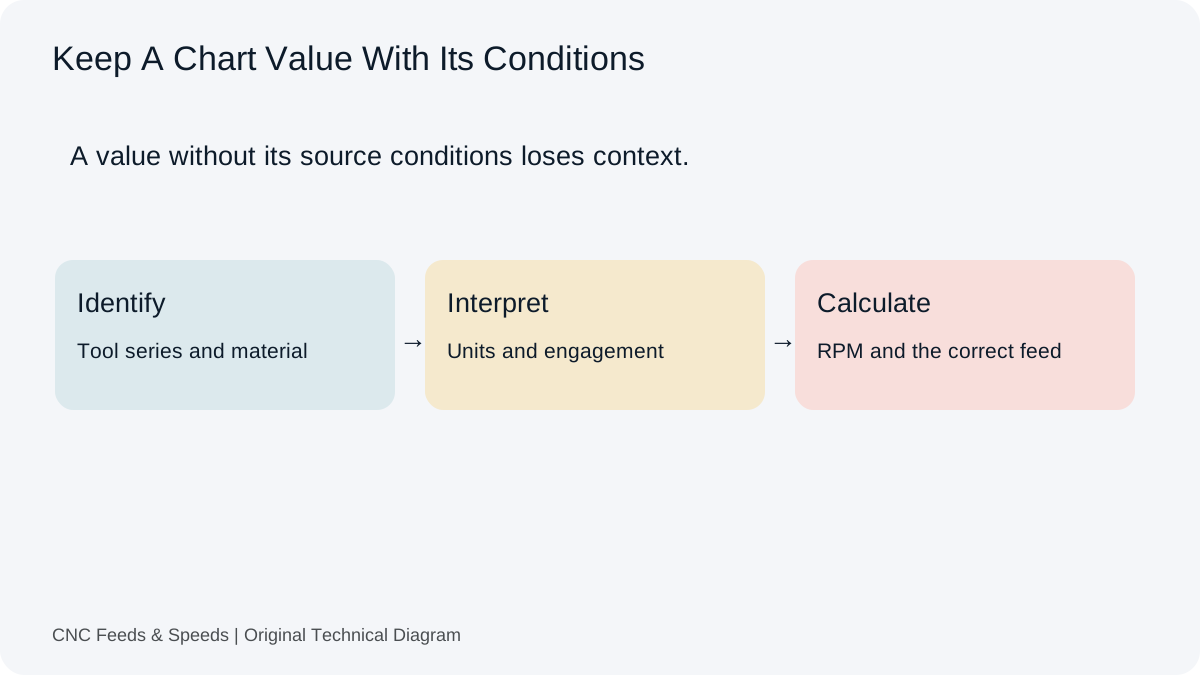
A fixed fraction of side-cutting feed can appear reassuring because it reduces a number. It still leaves the entry geometry, source feed basis, material and chip evacuation undefined. Two tools with the same diameter can have different entry limits. Two pockets can expose the same tool to different contact and clearance. A reduction without a valid starting condition does not establish suitability.
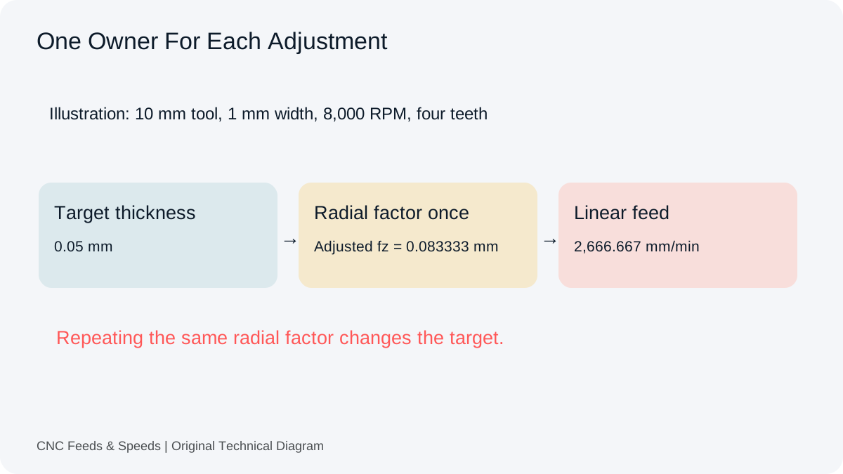
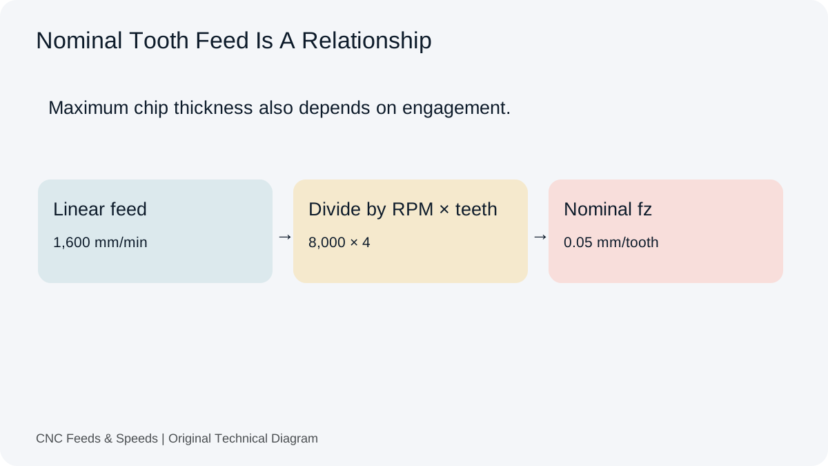
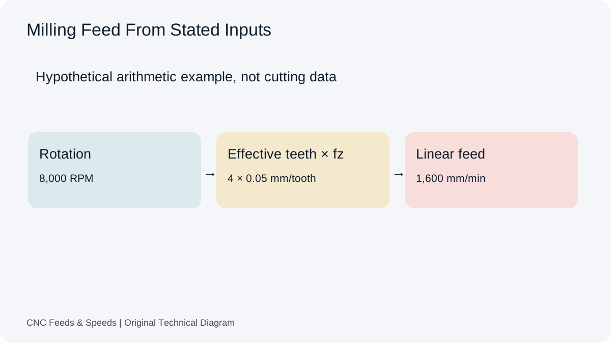
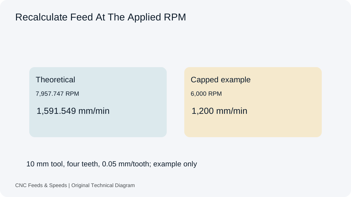
Keep the source tooth feed and spindle speed visible when you review the main cutting command. The milling feed-rate calculator checks their relationship. It does not select a plunge feed, a ramp angle or a manufacturer reduction. Where entry data is missing, resolve that omission with the appropriate tooling guidance instead of inferring a universal value from the side-cutting result.
Chip Evacuation Can Decide The Entry
An entry into enclosed material may give chips less space to leave than an open side cut. Material adhesion, tool chip space, coolant access and the depth reached can change the result. A mathematically gentle feed does not guarantee a clear cutting zone. Entry problems deserve a review of the actual chips and tool condition, not only the number entered into CAM.
The pocket chip-recutting article explains how trapped chips can create a problem even when a feed calculation is consistent. It also separates pocketing from drilling and boring. Keep those distinctions when choosing an entry: a successful method in an open pocket is not automatically suitable inside a small enclosed feature.
Review What The Posted Program Will Do
Inspect the entry path in CAM and verify its interpretation in the target program. Establish the active units, the feed assigned to the entry and the point at which the main cutting feed begins. Look for transitions, re-entry and repeated moves rather than checking only the first descent. Follow the machine’s established simulation and prove-out procedure before a new entry strategy reaches production.
If a feed override or a post change is involved, record it with the result. Otherwise a later programmer may reproduce the CAM inputs while the machine receives a different command. The calculation is only one part of a reproducible operation. Our setup-record guide covers the source, version and observed-condition details needed to preserve the rest of the workflow.
Keep Time Estimates Within Their Model
A ramp is longer than its horizontal projection, and a helix includes axial travel as well as circumference. Short entries may also spend much of their time below the commanded velocity. Dividing pocket depth by the main feed therefore does not estimate the complete entry. Use the time-scope guide to keep feed travel, CAM estimates and observed cycle time separate.
Once the intended method is established, record the actual path dimensions, tool specification and entry data together. That creates a useful starting point for later review without presenting one successful job as a universal recipe. If the material, tool reach or entry geometry changes, reopen those assumptions rather than carry forward a percentage that has lost its original context.
Entry Questions
Is A Lower Plunge Feed Always Acceptable?
No. The tool must be suitable for the intended axial entry. A lower command cannot provide missing cutting geometry or chip clearance.
Can I Use Finished Hole Diameter In A Helix-Angle Calculation?
Use the explicitly defined tool-centre path diameter for that calculation. Finished feature and centre-path diameters are different quantities.
Does The Site Select An Entry Strategy?
No. Its calculators check stated relationships. Toolmaker guidance, feature geometry and machine procedures determine the appropriate entry.
Help Improve This Resource
Request A Tool
Describe the calculation your workflow needs, the inputs you already have and the output you want to check. Include units and an example without confidential job details.
Request A ToolReport An Error
Share this page address, the entered values and the result you expected. Include the source of your comparison so the formula, units and explanation can be investigated.
Report An ErrorCNC Feeds & Speeds Editorial Desk
The site brings calculation tools and machining references into one workspace. Use the editorial and site information to understand its purpose and limitations. Send corrections with a reproducible example through the error report form.