Check lathe RPM and feed per revolution at the actual diameter, with CSS and timing limits explained.
Lathe RPM From Surface Speed
Use workpiece diameter at the cut to convert surface speed to RPM. In the second panel, compare linear feed with actual RPM to recover feed per revolution. This turning workspace keeps the diameter and feed convention visible when reviewing a lathe program.
Used For
Check conventional lathe speed and feed at a stated workpiece diameter.
Formula
RPM = 1000 × Vc ÷ (π × workpiece diameter). Linear feed = actual RPM × feed per revolution.
Spindle Speed Basic
Enter the values you know. The result is calculated in your browser.
Calculation only. Verify toolmaker data, material grade, engagement, machine limits, workholding and actual cutting conditions before production.
Turning Feed Per Revolution Check
Use the fuller calculation when additional process and machine variables matter.
Feed Per Rev Advanced
Enter the values you know. The result is calculated in your browser.
Calculation only. Verify toolmaker data, material grade, engagement, machine limits, workholding and actual cutting conditions before production.
Turning Quick Tools
Check linear feed, removal volume and straight-pass travel time without changing the main turning calculation. Keep workpiece diameter and actual RPM with each result. A changing CSS condition or facing profile needs more than a single steady-cut estimate.
Convert Turning Feed To Linear Feed
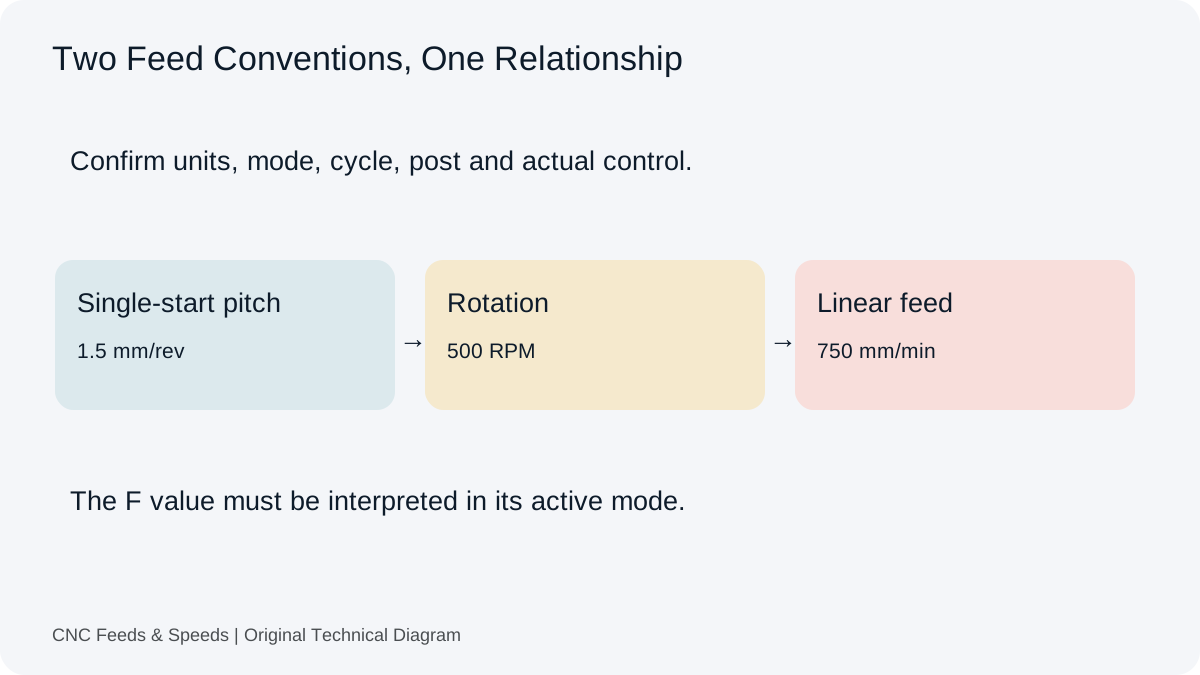
Calculate feed per minute from actual spindle RPM and source feed per revolution. Use the result to compare a steady turning pass or estimate time. Confirm the control feed mode before transferring a value into a program.
Open Turning Feed Tool
Linear feed = actual RPM × feed per revolution. Example: 1,000 × 0.20 = 200 mm/min.
Turning Linear Feed
Enter the values you know. The result is calculated in your browser.
Calculation only. Verify toolmaker data, material grade, engagement, machine limits, workholding and actual cutting conditions before production.
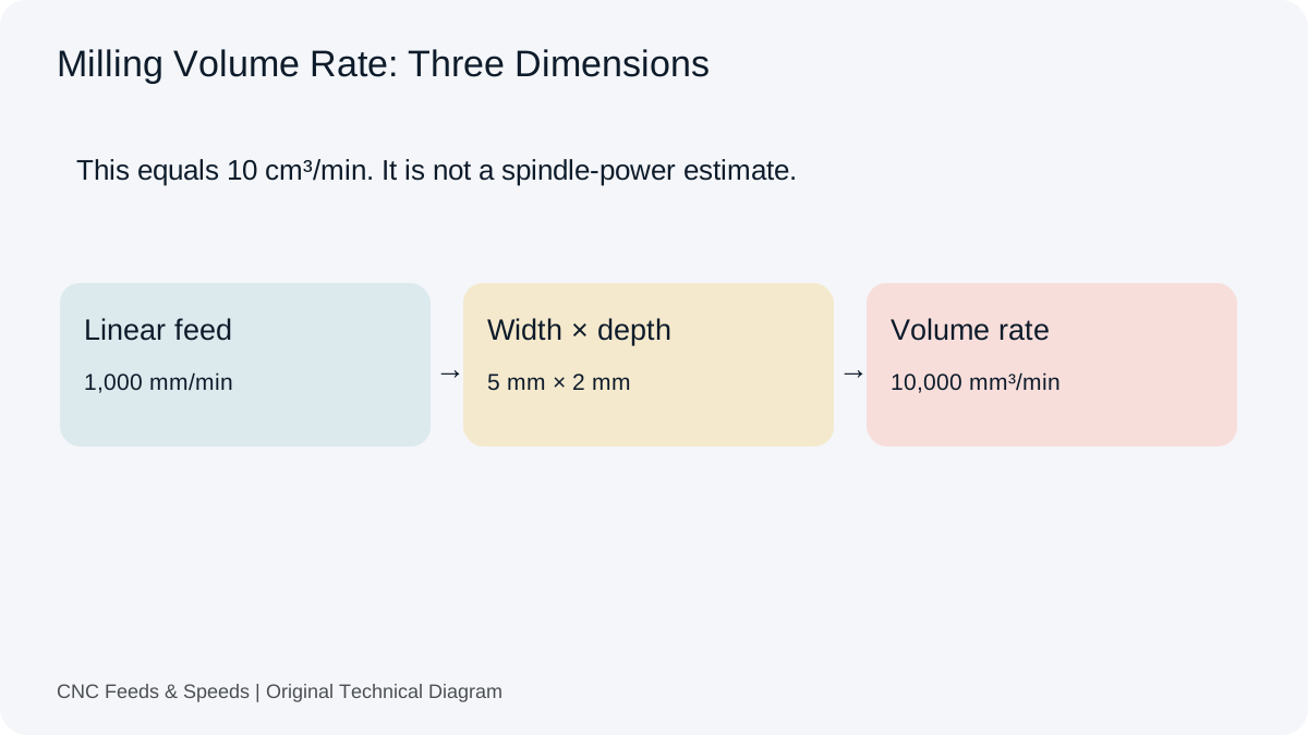
Use surface speed, radial depth and feed per revolution for a simplified turning volume rate. Enter radial depth rather than the full diameter reduction. The result describes removed volume and does not establish available spindle power.
Calculate travel time after converting the selected feed per revolution to linear feed. The model assumes that feed is maintained along the entered distance. It excludes acceleration, entries, retracts and changing spindle speed.
Open Turning Pass Time
Time = length ÷ (actual RPM × feed per revolution). Example: 100 mm ÷ 200 mm/min = 0.5 minute.
Straight Turning Travel Time
Enter the values you know. The result is calculated in your browser.
Calculation only. Verify toolmaker data, material grade, engagement, machine limits, workholding and actual cutting conditions before production.
Calculate the surface speed at a known workpiece diameter and actual RPM. Use it when reviewing a fixed-speed pass at another diameter. The result describes that condition rather than tracking an entire constant-surface-speed profile.
Open Turning Surface Speed
Metric Vc = π × workpiece diameter × RPM ÷ 1000. Example: 60 mm at 1,000 RPM gives 188.50 m/min.
Turning Surface Speed At Actual Diameter
Enter the values you know. The result is calculated in your browser.
Calculation only. Verify toolmaker data, material grade, engagement, machine limits, workholding and actual cutting conditions before production.
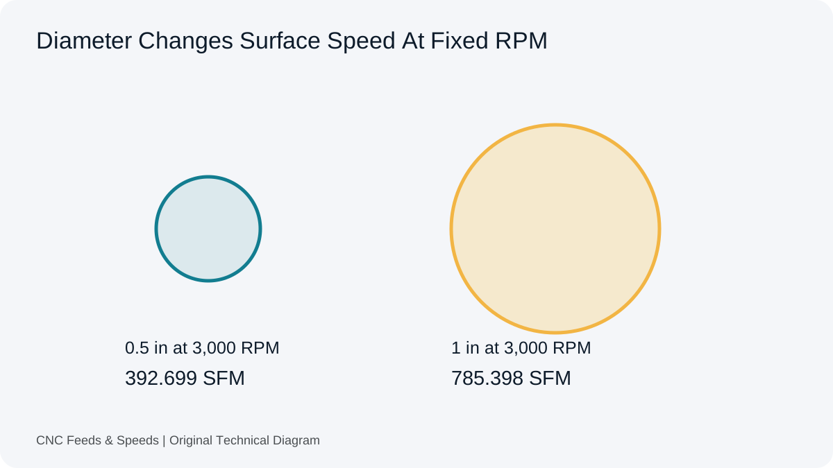
A turning speed and feed calculation uses the workpiece diameter at the cut. At fixed RPM, a smaller diameter has a lower surface speed. An RPM value from a previous operation therefore needs another check when the diameter changes, even if the material and insert remain the same. Use the cutting speed specified for the actual tool and application.
Check A Turning Condition
Choose Metric or Imperial and enter source cutting speed with the workpiece diameter in the basic panel.
Compare calculated RPM with the intended machine setting and spindle limit.
Use the Turning Linear Feed quick tool to multiply actual RPM by source feed per revolution. Use the second main panel to reverse-check that linear feed against actual RPM.
Read the control feed-mode requirements before transferring either feed value into a program.
A Turning Feed Calculation
At an illustrative 180 m/min and 60 mm diameter, RPM = 1000 × 180 ÷ (π × 60) = 954.93. A selected 0.20 mm/rev then gives 954.93 × 0.20 = 190.99 mm/min. The reverse check is 190.99 ÷ 954.93 ≈ 0.20 mm/rev. These inputs explain the relationships; they do not specify a suitable insert or cutting condition.
If the same 954.93 RPM is used at 30 mm diameter, surface speed falls to about 90 m/min. Holding 180 m/min at that diameter would require roughly twice the RPM, subject to the machine and program limits. The cutting speed calculator checks the actual surface speed at a known diameter and spindle setting.
Constant Surface Speed Is A Control Condition
Constant surface speed (CSS) can change RPM as the cutting diameter changes. A facing pass can approach progressively smaller diameters, so the permitted spindle ceiling matters. This page evaluates entered values at a stated condition. It does not simulate CSS through a profile, select a maximum spindle setting or generate G-code.
Feed, Removal Volume And Time
Use the turning MRR calculator when surface speed, radial depth and feed per revolution are known. For a straight constant-feed pass, convert feed per revolution to feed per minute before using the cutting time estimate. A complete lathe cycle also includes entries, retracts and other motions outside those steady-cut models.
A conventional circular nose leaves a repeating geometric trace as the work advances by one feed per revolution. This model checks the peak-to-valley height between those traces. It does not convert a drawing’s Ra or Rz requirement into an approved feed, and it excludes wiper inserts, vibration, wear and built-up edge.
Feed And Nose Radius
Use the radius of the conventional circular cutting nose and feed per revolution in matching length units. A larger ideal radius or a smaller feed changes the trace geometry. The same change can also affect the physical cut, so a geometric improvement is not evidence of a stable setup.
Formula
Exact trace height h = r − √(r² − (f ÷ 2)²). The small-feed approximation is h ≈ f² ÷ (8r). For a 0.8 mm nose radius and 0.20 mm/rev, the exact height is approximately 6.275 µm; the approximation is 6.25 µm.
Interpretation
The tool reports ideal peak-to-valley trace height and the approximation in µm or µin. These are geometric outputs, not a surface inspection result. Compare the actual part against the drawing with an appropriate measurement method rather than applying a universal conversion between roughness parameters.
Theoretical Turning Trace Height
Enter the values you know. The result is calculated in your browser.
Calculation only. Verify toolmaker data, material grade, engagement, machine limits, workholding and actual cutting conditions before production.
For this conventional turning calculation, enter workpiece diameter at the cut. Tool nose radius and insert geometry are separate inputs to the machining process.
Does Feed Per Revolution Change Automatically With A Feed-Per-Minute Command?
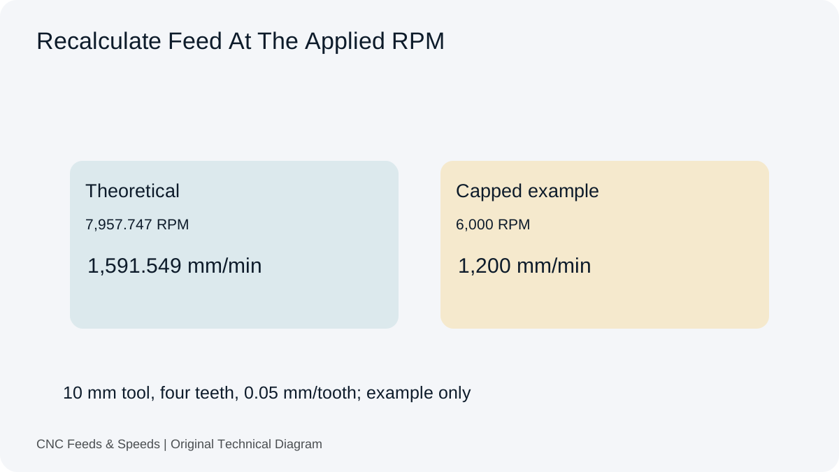
At a fixed linear feed, changing RPM changes the implied feed per revolution. The active control mode determines how the machine interprets a program value; check its documentation.
Can I Use This For Threading?
The surface-speed relationship can check a stated diameter and RPM, but the page does not establish threading feed, infeed strategy or cycle settings. Thread geometry and control instructions need their own review.
Help Improve This Resource
Request A Tool
Describe the calculation your workflow needs, the inputs you already have and the output you want to check. Include units and an example without confidential job details.
Share this page address, the entered values and the result you expected. Include the source of your comparison so the formula, units and explanation can be investigated.
The site brings calculation tools and machining references into one workspace. Use the editorial and site information to understand its purpose and limitations. Send corrections with a reproducible example through the error report form.
Related Articles
Continue with the calculation, setup or troubleshooting question closest to your task.
When A Router Cannot Run Slowly Enough To Drill
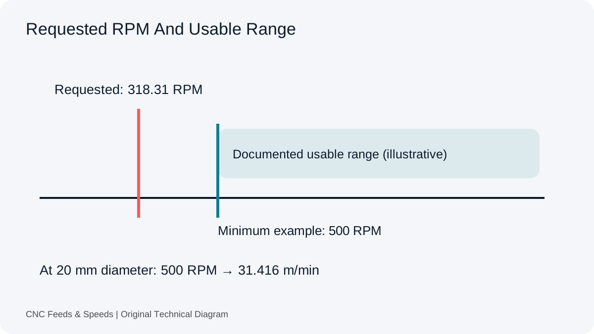
Compare drill requirements with the usable spindle range. Calculate achieved cutting speed without treating feed adjustment as a cure for incompatible tooling.